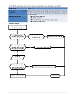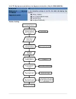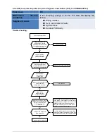
9.3.2.10 P4(IPM module protection) error diagnosis and solution.
Error Code
P4
Malfunction decision
conditions
When the voltage signal that IPM send to compressor drive
chip is abnormal, the display LED will show “P6” and AC will
turn off.
Supposed causes
●
Wiring mistake
●
IPM malfunction
●
Outdoor fan ass’y faulty
●
Compressor malfunction
●
Outdoor PCB faulty
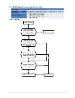
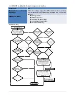
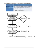
Trouble shooting:
IPM module protection
Check whether the voltage
range of P-N on IPM module is
normal? DC277-356V for 18-
27KBtu/h; DC277-410V for
36KBtu/h
Yes
Yes
No
Yes
Check whether the
input power supply is
correct? 220-240V, 1N,
60Hz
No
No
Regulate it to correct,
then check whether the
system can work
normally?
Check whether the
power supply line is
connected correctly
and tightly
Yes
Connect it correctly
and tightly, check ok
or not?
No
Check whether the
connecting line between main
board and the IPM module is
connected tightly
Yes
Connect it tightly,
check ok or not?
No
No
No
Connect it well,
check ok or not?
Check whether the
connecting line of the
compressor is connected
correctly or tightly
Replace the IPM module,
check whether the system
can work normally?
No
No
Replace the main board;
check whether the system
can work normally?
No
Replace the compressor,
check whether the system
can work normally?
Yes
Yes
Check whether the
lines in E-part box are
connected tightly
Yes
Connect it tightly,
check ok or not?
No
No
Yes
No
Replace the bridge rectifiers
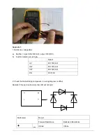
Check whether the bridge rectifiers
are normal? Use the multimeter to
measure the resistance between
each two terminals, check whether
there is the condition that value of
resistance is 0
Check whether the connecting line of
every reactor is normal? If the line is
broken, the resistance of the two
ports is ∞
(
models except for M4OC-
36HRDN1-M
);
Check whether the
PFC module broken (for M4OC-
36HRDN1-M)
Replace the connecting line or
reactor or replace the PFC
module(for M4OC-36HRDN1-M)
Yes
No
No
Yes
Trouble is solved

