background image

Page

 | 61


INNOFLIGHT


INTERNATIONAL


GALAXY


950


/


GALAXY


1080HL


MANUAL

 | Version 1.5 


the GCS cannot be established. The pilot should always land the Galaxy in GPS Mode 
(recommended) to have full control of the landing process. During landing no lateral 
movements  should be  conducted below 1.5 meters  AGL  off the ground.  If the 
aircraft is below 1.5 meters and is not over the desired location the pilot should raise 
the Galaxy to over 1.5 meters, move laterally and then proceed again following the 
recommended landing and shutdown procedure.  


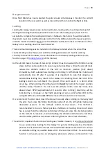
Recommended landing procedure 

1-


Decision made to start landing procedure  

2-


Start decent to landing location  

3-


Confirm landing area is clear  

4-


Check flight data on telemetry screen  

5-


Descend to 1.5m AGL 

6-


Check all flight controls including altitude raises (this will confirm not RTL is 
activated) 

7-


Lower the Galaxy to less than 1m AGL and confirm ground is clear  

8-


Lower the altitude control slowly until touch down 

9-


Hold the altitude control all the way down immediately upon touch down, DO NOT 
raise the altitude control until the Galaxy has disarmed/RPM decreased  

10-


While holding the altitude control fully down immediately on touch down it is also 
recommended to press the start/stop button to speed up the disarming of the 
Galaxy. Continue to hold down the altitude control for 10 seconds while the rotor 
RPM decreases 

Flight Characteristic tuning  

The Galaxy 950/1080 autopilot is specifically tuned to each Galaxy aircraft. Every aircraft has 
slight individual characteristics that require varied tuning from the default values, however 
environmental conditions also influence the flight performance as well as different payload 
weights. It is possible to make minor changes to the autopilot settings to enhance the 
performance of the Galaxy when changing payloads or to adjust for different environmental 
conditions.  

It is extremely important that the following settings are adjusted with care. Applying a large 
adjustment to any of the autopilot settings could result in unstable flight and catastrophic 
consequences.  It is recommended to consult your nearest distributor or directly 
communicate with Innoflight when adjusting the autopilot settings.  

Содержание GALAXY 1080HL

Страница 1: ...Page 1 INNOFLIGHT INTERNATIONAL GALAXY 950 GALAXY 1080HL MANUAL Version 1 5 GALAXY 950 GALAXY 1080HL Operating Manual ...

Страница 2: ... Software 13 Assembly 14 Landing Gear 14 Boom Assembly 15 DRS 10 Parachute installation 15 Boom Removal 15 Canopy 17 Main Blades 18 Testing Blade Tension 18 Landing Sensors 19 Maintenance 19 Checking the sensors 20 Autopilot LED indicator 21 Interface control 21 Connecting Landing Sensors 22 Battery System and MTOW 23 Galaxy 950 total payload plus battery must not exceed 10kg 23 Galaxy 1080HL tota...

Страница 3: ...e 25 Lost Link 26 Navigation Failsafe 27 GPS Lost 27 Autopilot LED status 27 All Lights on 27 Green 28 Blue 28 Red 28 Green and Blue 29 Compass Calibration 29 Declination 30 Entering Compass Calibration Mode 30 GPS Tracking 31 Geofencing 32 Altitude Limit 32 Distance Limit 32 Recovery Parachute DRS 10 34 Automatic activation parameters 35 Installing the DRS 10 to the Galaxy 950 35 Manual activatio...

Страница 4: ...y Additional Data 45 Connection to Galaxy 45 Flight Planning 45 Plotting flight plan area 46 Grid Planning 47 Adjusting Grid parameters 47 Camera settings 47 Shutter speed 47 Route Angle 47 Route Width 48 Safe Area Width 48 Hold Time 48 Flight Speed 48 Altitude 48 Camera trigger distance 48 Completing flight planning 49 Additional I GCS information 49 Loading Pre existing Missions 49 Read Waypoint...

Страница 5: ...ect Area 52 Importing a Shape File 53 Creating a Survey Grid 53 Simple Options Tab 53 Display 54 Boundary 54 Markers 54 Grid 54 Internal 54 Footprints 54 Advance Options 54 Grid Options Tab 54 Distance between lines m 54 Overshoot m 54 Lead in 55 Start From 55 Overlap 55 Side lap 55 Cross Grid 55 Camera Config Tab 55 Accepting a Survey Grid 55 Saving and Loading a Flight 55 Saving and Loading Flig...

Страница 6: ...past Midway 65 59 Transit 59 Navigation mode 60 Landing 60 Flight Characteristic tuning 61 Rotor head Gains 62 Tail Rotor Gains 62 Flight Data logging 63 Downloading Flight Logs 63 Georeferenced photolog 64 Autopilot log storage 65 FAA Part 107 Guidelines USA 65 Introduction The following procedures are intended to promote safe efficient and lawful operation of Innovative Flight Remotely Piloted A...

Страница 7: ...de the set parameters the parachute will automatically deploy It is possible for the user to manually fire the parachute if needed as explained on page I 22 of this operating manual The parachute system is not a guarantee for a safe recovery it is there to provide an additional safety measure in the unlikely event of an incident to reduce the risk of damage to people and property The parachute doe...

Страница 8: ...sion 1 5 Travel case Included Items 1 Travel Case 2 Boom Assembly 3 Landing Leg right 4 Ground Control Station 5 Assembly Tool 1 5mm 2mm 2 5mm 3mm Allen Key 6 DRS 10 Parachute 7 LiDAR Scanner Not included 8 Landing Leg left 9 Galaxy 950 1080HL Body 10 Main Rotor Blades ...

Страница 9: ...nection Plugs Tail DRS 10 and GPS 5 Radio Communication Modem FCC 15 247 Compliant 900mhz 6 Main Rotor Blades 7 Canopy Shell 8 Battery 9 XT90 Main battery connectors 10 Landing Legs 11 Rotor Head Specifications Length 1800mm 71 Width G950 550mm 21 6 Width G1080HL 755mm 29 7 Height G950 580mm 23 Height G1080 700mm 27 5 Centre of Gravity Between 85mm 3 35 forward of the rotor head and 40mm 1 6 aft o...

Страница 10: ...LAXY 950 GALAXY 1080HL MANUAL Version 1 5 To check the Centre of Gravity CG Balance rotate the main blades to be 90 degrees to the main body Place your fingers on the landing gear and adjust the forward and aft to check balance location ...

Страница 11: ...Page 11 INNOFLIGHT INTERNATIONAL GALAXY 950 GALAXY 1080HL MANUAL Version 1 5 ...

Страница 12: ...Press to Arm 8 3 Axis Joystick left right forward back Yaw 9 Altitude Control The Ground Control Station can be used with any windows operating system that has Bluetooth we recommend the Microsoft Windows Surface Pro tablet for compact size and long battery life Pairing Tablet to GCS To pair the tablet to the GCS open the Bluetooth settings and select pair new device With the GCS powered on you wi...

Страница 13: ...long range FCC approved 900 MHz data modem For BVLOS Beyond Visual Line of Sight operations it is possible to use 2 GCS systems and Daisy chain them to the Galaxy to allow extended flight operations The diagram below shows how two pilot teams could conduct a 10km or further corridor flight Pilot in Command 1 PIC1 will take off at around 4km PIC 1 will communicate with PIC 2 and pass over control o...

Страница 14: ...ed in two halves left right they are attached to the leg clamp mounts already attached to the main body Once the square carbon legs have been installed they are held in place by tightening the 4 M3 bolts on each leg clamp When tightening the bolts take care not to over tighten them Apply a small amount of 243 Loctite to each bolt to lock in place Each landing leg has a sonar sensor that is connect...

Страница 15: ...rtical fin is parallel to the main rotor shaft and the GPS plate is level Once the boom is locked in place connect the three connection plugs for the GPS DRS 10 and tail motor DRS 10 Parachute installation Refer to Page 27 of this manual for DRS 10 information and installation Boom Removal The boom can be easily removed for transport by loosening the bolts and disconnecting the plugs once disconne...

Страница 16: ...Page 16 INNOFLIGHT INTERNATIONAL GALAXY 950 GALAXY 1080HL MANUAL Version 1 5 ...

Страница 17: ...ly and locate on the mounting posts Bolt in place using M3 Bolts The rear section of the canopy is joined with a clear piece of cello tape The canopy is not essential for flight it is possible to fly without the canopy The canopy provides additional protection from the environment and makes the Galaxy more aerodynamic however it is an additional weight and therefore reduces the flight time slightl...

Страница 18: ...ades can fold when pushed back but not so loose that they have lag and cause vibrations Testing Blade Tension To test the blade tension straighten the main blades out and tilt the Galaxy on its side the main blades should stay level If you jolt the Galaxy slightly the blades should just start to droop If you turn the galaxy on its side and the blades fall instantly they are too loose ...

Страница 19: ... take off and landing of the Galaxy aircraft Before each flight it is important to check that the sensors are operating correctly The Galaxy must not be operated without the landing sensors working correctly Maintenance The Landing sensors use a laser return signal to measure distance it is critical that the clear glass face of the landing sensor is always kept clean allowing a clear return signal...

Страница 20: ...stating ground switch error The landing sensors feature two LED s on each sensor one green and one yellow With the Galaxy powered on the Landing Sensor LED will indicate Green and Yellow combined for less than 50mm and Green only for greater than 50mm this indicates that the sensors are working correctly There are also two LED s located on the Autopilot the two LED s are related to each sensor lef...

Страница 21: ...ng correctly lift the Galaxy over 50mm 2 by rotating the nose forward to raise the rear landing gear and landing sensors Below is an image of the autopilot LED both LED 1 2 are illuminated indicating that the landing sensor detects above 50mm or that sensor is not connected to the autopilot Interface control The Landing sensors can be disabled to troubleshoot you should never operate the Galaxy wi...

Страница 22: ...ch Enable this must be turned on for the landing sensors to be active Connecting Landing Sensors The Landing sensors are connected to the Galaxy via an 8pin MPX connector there are two connectors left right to allow both landing sensors to be connected Also located on this connector is a 2 pin auxiliary port that can be used to output a PWM signal to trigger camera shutters or control third party ...

Страница 23: ...ceed 12kg Battery 30 000mah 7kg total allows 5kg max payload Battery 22 000mah 5kg total allows 7kg max payload Battery 16 000mah 4kg total allows 8kg max payload Recommended Batteries Galaxy 950 Galaxy 1080HL Capacity 12 000 30 000mah x2 Voltage 6s 6 cells 22 2volts Ground Control Station Capacity 3000 4500mah Voltage 2s 6s 2 cells 7 4volts 6 cells 22 2volts Landing Voltages While operating the G...

Страница 24: ... loop strap that holds them to a solid carbon plate Once the batteries are strapped in place connect each battery to the corresponding XT90 plug mounted on the main body sides When connecting the XT90 to the Galaxy always confirm the plug is pushed in firmly Failure to push the plug all the way in could result in a loss of power to the entire system including the parachute Charging The batteries s...

Страница 25: ...urn home when this is activated the stage 2 failsafe does not consider the distance from home so it is important that cautious battery monitoring is conducted during all flights BVLOS or Corridor missions we recommend that stage 2 is disabled This is due to the fact the Galaxy could be far from the original take off location when RTL Return to launch is activated in most cases there would not be e...

Страница 26: ...bstacles in case an emergency landing is required Lost Link If during a flight the communication link between the GCS and the Galaxy is disconnected the autopilot can be configured to delay from 0 to 120seconds before returning to launch RTL is activated A delay is useful when flying around terrain where a failsafe may be unsafe if activated Using the PC interface connect to the autopilot via USB ...

Страница 27: ...ound terrain where an RTL would be unsafe example close to high trees or terrain Careful flight planning must be used to avoid flying missions that could exceed the battery capacity resulting in a loss of power to the Galaxy GPS Lost If during flight the GPS satellite link is lost the autopilot will delay a set time configured in the PC interface before beginning to decent and land Autopilot LED s...

Страница 28: ...termittent Green Autopilot off Attitude mode Flashing Green Establishing satellite connections Compass Calibration Intermittent or Solid green at the completion of compass calibration dependent on AP switch Blue Flashing Blue No GPS satellites established Solid Blue Compass Calibration mode Red Intermittent Red Sensor Error Flashing Red Battery low failsafe Solid Red GPS not connected ...

Страница 29: ...uring Compass Calibration Indicates phase one of compass calibration is completed Compass Calibration Compass Calibration will be performed as required It is necessary to perform compass calibration if the Galaxy has moved more than 200 miles from its last site of compass calibration or if the magnetic declination has changed from its last calibration ...

Страница 30: ...Puck to flash green continuously When conducting a compass calibration always make sure that the DRS 10 is in the unloaded position silk removed and deployment plate released to avoid the system activating and damaging the carbon structure of the DRS 10 To enter Compass Calibration mode Use the autopilot mode momentary switch Press and release the switch fast 4 times to enter calibration mode The ...

Страница 31: ...y back on the ground wait three seconds before removing power Re power the Galaxy as per normal procedure and continue with pre flight checks GPS Tracking If during flight you observe the Galaxy to be flying slightly crabbed angled the calibration or declination value may need to be adjusted First repeat the compass calibration process if the crabbing is still observed adjust the declination 1 deg...

Страница 32: ...e height limit is set to 120m 400ft but the take off height is 400m 1300ft MSL if the autopilot height source is set to GPS MSL then the take off location is already exceeding the height limit and will not take off correctly If the autopilot is set to Barometric AGL then the height limit will work correctly as no matter where the take off location is the barometric height will always initialize at...

Страница 33: ...he gains settings and caution must be used when changing the RPM values and flight testing only change from default under the guidance of your distributor and or the manufacturer Innoflight International pty ltd Default starting points for RPM Payload RPM RPM Windy 0 3kg 52 000 55 000 55 000 57 000 3 4 5kg 55 000 60 000 60 000 62 000 4 5 6 5ks 62 000 65 000 65 000 67 000 Adjusting the RPM Connect ...

Страница 34: ...arachute DRS 10 The Galaxy 950 is equipped with a recovery parachute that is attached to the boom The parachute is manufacture by Drone Rescue Systems for use with the Galaxy 950 The recovery chute is activated electronically and released via rubber straps under tension this allows the system to be transported easily as no pyrotechnics or compressed air cartridges are used The parachute is excepti...

Страница 35: ... 1 5 Automatic activation parameters Exceeds 70 degrees of pitch or roll angle Decent rate of more than 6m s for longer than 0 5 seconds Effective from 35 meters AGL Installing the DRS 10 to the Galaxy 950 The DRS unit is attached to the boom via two M3 bolts as shown below ...

Страница 36: ...ng a spine there are two holes that are fitted with a threaded insert The two attachment bolts need to go through the first rail boom mount and second rail The bolts need to be tightened firmly to clamp the DRS 10 in place securely Once the DRS 10 is bolted in place connect the 5 pin connector to supply power and signal to the system ...

Страница 37: ... the weight of the silk being removed it is recommended to use a weighted object to avoid damaging the carbon fibre structure of the DRS 10 A simple filled water bottle installed in place of the parachute silk is recommended Automatic Activation Test Due to the Galaxy rotor head design it is only possible to test the automatic activation of the parachute by following the compass calibration proced...

Страница 38: ...k will simulate this DRS 10 LED Status The DRS 10 utilises an external LED used to indicate the system status Mechanically Arming the DRS 10 With the Galaxy 950 de powered use your finger to lift the white locking arm located on the outside of the DRS 10 Using the water bottle or a tube that fits inside the DRS 10 push the carbon fibre plate all the way into the DRS 10 you will feel the tension of...

Страница 39: ...Page 39 INNOFLIGHT INTERNATIONAL GALAXY 950 GALAXY 1080HL MANUAL Version 1 5 ...

Страница 40: ...and to hold the package together To install the silk into the DRS 10 carefully hold the package together and remove the rubber band Slide the silk and cardboard into the DRS 10 tube with the folded edge of the cardboard going in first Push the assembly into the tube until it is all the way in The join where the cardboard meets itself should be positioned along the carbon rail mount of the DRS 10 a...

Страница 41: ... parachute After the days flying it is recommended to remove the parachute silk from the DRS 10 and release the firing plate to relieve the rubber bands of their tension When releasing the deployment plate always insert a weighted object or hold force against the plate to prevent the carbon fibre structure being damaged by the release force Store the parachute silk inside the carboard sleeve with ...

Страница 42: ...t system is not possible through this software and must be done via separate software that connects directly to the autopilot hardware Installation To install I GCS you will need to copy or download the installer to the Windows based computer you will be flight planning or operating the Galaxy from Run the installer as administrator and follow the prompts to complete the install General Setup Afte...

Страница 43: ...ndow will appear with options to change the values Select the values desired and close the window by clicking x the values will save automatically Telemetry Data It is required to customize the telemetry and system options to your preferences Below is a guide based on the recommended settings for operating the Galaxy ...

Страница 44: ...add delete these values as well as add additional options and change the order of the telemetry data displayed Telemetry Data To add or change the values displayed right click one of the telemetry data values A box will appear with the options to Add Info and Delete Info In the attached images to this manual you will see the recommended telemetry data to be operate the Galaxy aircraft ...

Страница 45: ...st have the Ground Control Station paired to the windows computer being used For information on this process go to page 11 of this manual Located at the top right of the screen is connection click this to bring up the window to allow connection select the correct com port to initiate the connection Once connected the telemetry values will change to reflect the Galaxy data being transmitted Flight ...

Страница 46: ...lect the Place area point Icon the first point clicked will drop a home point this can be moved around by dragging the H icon After the home point has been set the next points will place a red pin and a shape file will start to be drawn and you add more pins The outline can be altered by dragging the pins to edit the selected flight area ...

Страница 47: ...settings If you know the camera settings for your payload it is possible to add the focal length sensor width and sensor height This allows the automatic settings for percentage side lap and forward lap to be calculated depending on the height selected Shutter speed To set the shutter speed time between camera triggers the Photo Overlap value can be adjusted The shutter interval time in seconds wi...

Страница 48: ...ld Time value can be set Adjusting this value will set a time delay for the galaxy to stop at each individual waypoint Flight Speed Set the flight speed of the Galaxy The flight speed specifications for the Galaxy is 0 5 meters per second m s to 15 meters per second m s Operating over 15m s is not permitted inside standard operating specifications Altitude Set the altitude to be flown Camera trigg...

Страница 49: ...tion Loading Pre existing Missions It possible to load pre planned flights using the Load waypoints option This will open a windows folder browser navigate to the selected waypoints file selected the file The pre planned mission will load and be able to be written to the Galaxy The same process can be followed with opening pre planned area files Select the Load Area option This will open a windows...

Страница 50: ...utopilot system is not possible through this software and must be done via separate software that connects directly to the autopilot hardware Installation The software comes pre installed on the Ground Control Station GCS You may receive an additional copy of the software which may be installed on local machines Windows based environment for the of purpose flight planning Files The install comes a...

Страница 51: ...to follow the user must select the FLIGHT PLAN screen button on the top left of the INF Planner window or by pressing the F3 key The map area becomes larger as well as flight data being removed By default the map region will default to the last geographic location in which a home location was set Select the map service provider location on the right hand side of the INF Flight Planner window in th...

Страница 52: ... planning phase it is recommended to select the anticipated launch point as the Home point for accurate depiction of flight path and time estimates Defining the Project Area To create a grid flight plan you must have the area predefined It is recommended to make the predefined area larger than the project area This is to guarantee coverage for processing There are two ways to define the area for t...

Страница 53: ... right click on the map and select Auto WP Survey Grid This will open a subwindow and automatically generate flight lines based on options listed in Simple and Grid Options Waypoints will be indicated by green markers with black numbering Flight lines are drawn in yellow between waypoints with direction of travel indicated mid flight line by arrow In this sub window the polygon may be amended by d...

Страница 54: ...markers for flight line start and end Grid Displays the flight line Internal Displays approximate camera triggering locations Footprints Displays approximate area of coverage for each camera capture Advance Options Turns on additional options tabs of Grid Options and Camera Configuration Grid Options Tab The Grid Options tab allows for the run spacing and camera overlap for imagery capture Distanc...

Страница 55: ...is tab should be referenced to verify the GSD Ground Sampling Distance of the chosen payload and ensure the side lap chosen will be sufficient for the data acquisition plan Accepting a Survey Grid Pressing the Accept button on the Simple Tab will close the Survey Grid sub window and transfer the flight lines to the main map region Saving and Loading a Flight Flight plans are saved as waypoints or ...

Страница 56: ...light 2 Microsoft tablet battery is at a suitable percentage 3 All switches work correctly 4 Joystick and Altitude control movement is free and without binding Flight Mission 1 Flight path is within the regulations 2 Home location is correctly set for a suitable location 3 Flight speed and path overlaps are correct for the data capturing Flight Operations Control Check Using the GCS joystick and a...

Страница 57: ...ton can now be used to disconnect from the aircraft Load a Flight Plan onto the Autopilot Loading a flight plan that has been created requires the operator to be on the Flight Plan screen in the software Once the operator has reviewed the flight lines the flight plan may be uploaded by clicking on the Write WPs button in the Action Pane DO NOT write WPs to the Galaxy without first setting the home...

Страница 58: ...here will be no new potential hazards If the environment has changed reassess the take off point s suitability for the project and isolate hazards It is recommended to take off with the heading of the Galaxy pointing directly away from you this allows you to react to control easily if needed There should be no obstacles or people within a 30m radius of the Galaxy during take off and landing ...

Страница 59: ...once the main rotor has started There is a 3 second delay between the tail rotor and main rotor spool up initiating Hold the Altitude control to past Midway 65 Either Increase Altitude control or Select NAV Mode if a mission has been uploaded written to the autopilot Depending on the risk factor the pilot may either transit the aircraft vertically to the first waypoint using the Altitude control o...

Страница 60: ...atically shut off after 5 seconds It is important to note that allowing an autonomous landing may result in the Galaxy not shutting down the rotor if the landing sensors do not detect the ground this could result in a boom strike occurring When landing the Altitude control MUST be held at the lowest position until the Galaxy disarms Do not raise the altitude control until the rotors have slowed do...

Страница 61: ...immediately upon touch down DO NOT raise the altitude control until the Galaxy has disarmed RPM decreased 10 While holding the altitude control fully down immediately on touch down it is also recommended to press the start stop button to speed up the disarming of the Galaxy Continue to hold down the altitude control for 10 seconds while the rotor RPM decreases Flight Characteristic tuning The Gala...

Страница 62: ...ntrol gains consist of two values Rudder Lock Gain and Rudder I Gain The default values for the Galaxy is 135 5 for the lock gain and 40 5 for the I gain There are situations where these settings may need to be adjusted to meet the user requirements or environmental conditions such as wind The tail rotor control is very forgiving to adjustments compared to the rotor head increments of up to 10 per...

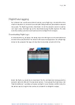
Страница 63: ...rs and must be sent to Innoflight for full analysis Downloading Flight Logs To download this log de power the Galaxy Open the INF log tool on the GCS tablet and connect to the autopilot USB The tool will self connect and populate a list of flight logs stored on the autopilot The logs will show the time and date armed in UTC time Select the flight you would like to download The file will download a...

Страница 64: ...otogrammetry processing This file records the autopilot data every time the autopilot commands a photo trigger The data is coma denominated and records the following information Latitude Longitude Height IMU data Heading and GPS time stamp To download this file select Georeference data and save the file A folder with open asking for save location and the file will be saved as a txt file ...

Страница 65: ...be responsible for more than one unmanned aircraft operation at a time You can fly during daylight 30 minutes before official sunrise to 30 minutes after official sunset local time or in twilight with appropriate anti collision lighting Minimum weather visibility is three miles from your control station The maximum allowable altitude is 400 feet above the ground higher if your drone remains within...

Страница 66: ...ntrol station and the UAS Other Requirements If you are acting as pilot in command you have to comply with several other provisions of the rule You must make your drone available to the FAA for inspection or testing on request and you must provide any associated records required to be kept under the rule You must report any operation that results in serious injury loss of consciousness or property...

Страница 67: ...Page 67 INNOFLIGHT INTERNATIONAL GALAXY 950 GALAXY 1080HL MANUAL Version 1 5 ...

Отзывы: