


AFDJ-SVU01D-EN
55
Troubleshooting
Alarms
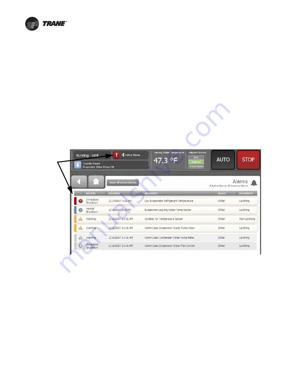
When an active alarm is present, it is identified in the
Active
Alarms
area in the upper left corner of the Tracer
AdaptiView display. This serves two purposes. First to
alert the operator that a alarm exists, and second to
provide navigation to the Alarms list.
Clicking on the active alarms causes the Alarms list to
display. All active alarms are listed first and ordered by the
alarm’s severity. The severity hierarchy is:
•
Immediate shutdown (highest priority and displays
first)
•
Normal shutdown
•
Warning
•
Unknown (lowest priority and displays last)
Active alarms are followed by any historical alarms. These
appear gray on the screen. The alarms button at the
bottom of the screen flashes between two colors
depending on the severity of the highest priority alarm
(i.e., Immediate shutdown alarms cause the button to flash
between red and black, and Normal shutdown alarms
cause the button to flash between yellow and black).
Clicking directly on any of the active alarms links to a
screen that explains the alarm and provides possible
solutions.
You can also connect the laptop computer loaded with the
Tracer TU service tool software directly to the UC800
controller to view the AFD last diagnostic code (refer to
for detailed information on which AFD
settings you can see using Tracer TU).
Troubleshooting
This section can assist in field troubleshooting
Communicating MV drives, and can provide information,
which others can use to help you troubleshoot the drive.
1.
Collect alarm and parameter information.
a. DO NOT cycle unit power or reset the controls.
Leave the AFD and the UC800 in their present
states.
b. Record the “AFD Last Diagnostic Code” using
Tracer TU. This value is available under the Unit
Status tab, in the AF (Adjustable Frequency)
expanding box.
c. Record all UC800 active and historic alarms. Make
a full chiller service report.
d. Document and check all applicable parameter
settings. This information can be verified off of the
chiller nameplate, and by referring to this manual.
e. In the Binding view of the Tracer TU service tool,
verify there is a green circle indicating that the AFD
Recomm Starter LLID is properly bound.
2. Collect Chiller Information.
a. Note the following chiller information:
•
Operating mode and any sub-mode (i.e.,
100 percent or 75 percent load etc.)
•
Number of chiller starts, and hours of operation.
•
Time since last diagnostic shutdown (<1 minute,
<1 hour, >1 hour, etc.)
Figure 48.
Tracer AdaptiView alarms screen
Active alarms
Содержание TRANE AFDJ
Страница 20: ...Cabinet 20 AFDJ SVU01D EN Figure 5 A Frame Door swing requirements...
Страница 22: ...Cabinet 22 AFDJ SVU01D EN Figure 7 A Frame Interior view major components in mm...
Страница 26: ...Cabinet 26 AFDJ SVU01D EN Figure 13 B Frame Interior view major components...
Страница 58: ......
Страница 65: ......


