background image

Form MHD56181

PARTS, OPERATION AND MAINTENANCE 

SUPPLEMENT*

MODEL FH5

* This supplement should be used in conjunction with supporting documentation for the
hydraulic motor, disc brake, reduction gear assembly and controls as applicable.

Form MHD56181
Edition 1
April 1999
71350573

© 

1999 Ingersoll-Rand Company

READ THIS MANUAL BEFORE USING THESE PRODUCTS. This manual
contains important safety, installation, and maintenance information. Make
this manual available to all persons responsible for the operation,
installation and maintenance of these products.

WARNING

Do not use this winch for lifting, supporting, or transporting people or lifting or
supporting loads over people.

Always operate, inspect and maintain this winch in accordance with American National
Standards Institute Safety Code (ASME B30.7) and any other applicable safety codes and
regulations.

Refer all communications to the nearest Ingersoll-Rand Material Handling Office or
Distributor.

Содержание Force 5 FH5

Страница 1: ...mportant safety installation and maintenance information Make this manual available to all persons responsible for the operation installation and maintenance of these products WARNING Do not use this winch for lifting supporting or transporting people or lifting or supporting loads over people Always operate inspect and maintain this winch in accordance with American National Standards Institute S...

Страница 2: ...ssembly 13 Automatic Disc Brake 14 Seals and Bearings 14 Drum Locking Pin 14 Wire Rope 14 Inspection Records and Reports 15 Frequent Inspection 15 Periodic Inspection 15 Winches Not in Regular Use 16 Inspection and Maintenance Report 17 Troubleshooting Troubleshooting Chart 18 19 Maintenance Maintenance Intervals 20 Adjustments 20 Hydraulic System General Maintenance 20 Disassembly Instructions 21...

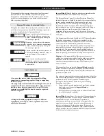
Страница 3: ...he load From a safety standpoint one factor is paramount conduct all lifting or pulling operations in such a manner that if there were an equipment failure no personnel would be injured This means keep out from under a raised load and keep out of the line of force of any load The Occupational Safety and Health Act of 1970 generally places the burden of compliance with the owner employer not the ma...

Страница 4: ...lift a load greater than the rated capacity of the winch Refer to SPECIFICATIONS section 6 Keep hands clothing etc clear of moving parts 7 Never place your hand in the throat area of a hook or near wire rope spooling onto or off the winch drum 8 Always rig loads properly and carefully 9 Be certain the load is properly seated in the saddle of the hook Do not tipload the hook as this leads to spread...

Страница 5: ...14 F or 20 C 4 F D Drum Divider Flange and additional wire rope anchor G Drum Guard L Drum Locking Pin M1 Material Traceability Typical material results M2 Material Traceability Actual material results M3 Material Traceability Actual material results for these parts in finished as delivered condition N Type Approval Specify A American Bureau of Shipping ABS N Det Norske Veritas DNV R Lloyd s Regis...

Страница 6: ...drum brake and winch drum The manual brake requires an operator to engage and disengage the brake using a lever located on top of the brake band The automatic drum band brake operation is similar to the disc brake with the following exception the automatic drum band brake fully disengages in both the haul in and payout directions General Specifications Model FH5 FH5T Utility Rating 5 1 design fact...

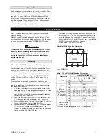
Страница 7: ...e winch 3 to 4 inches 75 to 100 mm off the ground Verify winch is balanced and secure before continuing lift Mount the winch so the axis of the drum is horizontal If the winch is to be mounted in an inverted position it may be necessary to reposition the motor parts 1 The winch mounting surface must be flat and of sufficient strength to handle the rated load plus the weight of the winch and attach...

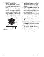
Страница 8: ...od of reeving Wire rope construction should be 6 X 19 or 6 X 37 IWRC right lay to permit correct installation of wire rope anchor Refer to Table 3 on page 8 for minimum and maximum recommended wire rope diameters Smaller wire rope sizes may be acceptable on custom designed drums Installing Wire Rope Refer to Dwg MHP0166 on page 8 1 Cut wire rope to length in accordance with the wire rope manufactu...

Страница 9: ... only If trouble is experienced due to the use of long hoses it may be necessary to use hoses which are one size larger Table 4 Hydraulic Hose Recommendations Hydraulic Fluid The most frequent cause of malfunction or failure of hydraulic equipment is the presence of contaminants in the hydraulic fluid Reduce contaminants by using clean hydraulic fluid and changing the fluid before it deteriorates ...

Страница 10: ...should have good metering characteristics in order to provide smooth winch control A built in relief valve suitable for maximum operating pressure and flow should also be installed in the control valve and or hydraulic system Motor For optimum performance and maximum durability of parts ensure hydraulic supply does not exceed recommended pressures and flows When feasible the motor should be instal...

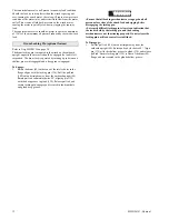
Страница 11: ...ss is extremely important to ensure safe continued operation of components Dirty or contaminated hydraulic fluid may cause components to break down operate erratically or damage valuable equipment Warm Up Procedure CAUTION A warm up procedure is recommended at each start up under normal operating conditions and is essential at ambient temperatures below 40 F 4 C To warm up the hydraulic oil and sy...

Страница 12: ...ove engaged To Engage 1 Rotate the drum 80 so that one of the twelve holes in the flange aligns with the locking pin 136 Pull the pull rod 140 out and straight away from the outboard upright 84 Rotate pull rod counterclockwise 90 aligning pin 135 with the deep groove in gland 138 Release pull rod and ensure locking pin engages and is seated in the drum hole and gland deep groove WARNING Ensure tha...

Страница 13: ...tly if desired 3 Always inspect removed oil for evidence of internal damage or contamination metal shavings dirt water etc If indications of damage are noted investigate and correct before returning winch to service 4 After winch operation allow oil to settle before topping off 5 Always drain oil into a suitable container and dispose of in an environmentally safe manner Oil Capacities Reduction Ge...

Страница 14: ...land 138 with 2 or 3 pumps of a grease gun If drum locking pin is disassembled clean all parts thoroughly and coat with clean grease Refer to the Recommended Lubricants section Use sufficient grease to provide a good protective coat Lubrication will help to prevent rust and allow easier locking pin operation Wire Rope Follow the wire rope manufacturer s instructions At a minimum observe the follow...

Страница 15: ...visual inspections should be conducted during regular operation for damage or evidence of malfunction 1 WINCH Prior to operation visually inspect winch housings controls brakes side rails and drum for indications of damage Do not operate the winch unless the wire rope feeds onto the drum smoothly and any discrepancies noted have been reviewed and inspected further by personnel instructed in the op...

Страница 16: ...ually test brakes installed to ensure proper operation Brakes must hold a 125 rated load at full drum without slipping If indicated by poor operation or visual damage disassemble and repair brake s Check all brake surfaces for wear deformation or foreign deposits If brake lining thickness is less than minimum as described in the MAINTENANCE section replace brakes Clean and replace components as ne...

Страница 17: ..._____________________________ Refer to the Parts Operation and Maintenance Manual INSPECTION section for general inspection criteria Also refer to appropriate National Standards and codes of practice If in doubt about an existing condition contact the nearest Ingersoll Rand Distributor or the factory for technical assistance COMPONENT CONDITION CORRECTIVE ACTION NOTES Pass Fail Repair Replace Upri...

Страница 18: ...her setting Refer to motor manufacturer s literature System not delivering full pressure to winch Confirm pump is running and on stroke Check upline flow controls are set as required to run the winch Relief valve dumps full pressure Confirm no downline restrictions of valves are blocking free flow back to tank Relief valve set too low Install pressure gauges in motor lines and apply a stall pull o...

Страница 19: ...essure for an adequate period of time to ensure pressure does not bleed down Automatic Disc Brake Brake fails to release Low oil supply pressure Ensure the oil pressure at the inlet to the disc brake is at least 300 psig 2069 kPa 20 7 bar Worn or damaged piston seals Inspect the brake breather If oil escapes from the brake breather when attempting to release the brake the brake seals must be repla...

Страница 20: ...handle 104 7 Install cotter pin 102 when adjustment is completed CAUTION When any part of the brake lining measures 0 062 inch 2 mm or less brake bands 128 or linings must be replaced Automatic Drum Brake Adjustment Refer to Dwg MHP0153 on page 28 1 Remove cotter pin 102 and washer 129 at adjustment clevis 107 2 Apply oil pressure to the brake cylinder 110 and remove pin 106 and second washer 129 ...

Страница 21: ... all clean out holes filler caps and breather cap filters on the reservoir are properly fastened 11 Do not run the system unless all normally provided filtration devices are in place 12 Make certain that the fluid used in the system is a type recommended by the manufacturers of the system or components The above recommendations are based on an open system equipped with micro air breathers Open sys...

Страница 22: ...21 so brake band halves 128 can be removed from the arm 124 Lower winch when brake band assembly has been removed 6 Refer to Brake Lining Instruction Sheet Form MHD56142 for brake lining replacement procedures Drum Reducer Removal Refer to Dwg MHP1777 on page 26 1 Remove capscrews 85 and lockwashers 86 which secure the side rails 82 and 83 to the inboard upright 42 Drive out dowel pins 87 2 Remove...

Страница 23: ... this step 6 Install shaft retainer 92 Secure by installing three capscrews 93 Lightly coat capscrew threads with Loctite 242 Torque to 30 ft lbs 41 Nm 7 Install spacer 91 8 Apply a light coat of Loctite 515 sealant to the mating surface of the outboard upright 84 and install end cover 95 Secure using six capscrews 97 and lockwashers 96 Lightly coat capscrew threads with Loctite 242 Torque to 30 f...

Страница 24: ...irm leak free connections 3 Install 0 3 000 psi 0 207 bar pressure gauges with gauge snubbers teed into the winch at or near the motor A and B ports Run winch with no load Record pressure in both directions Confirm winch hauls in when pulling throttle and pays out when pushing throttle Ensure controls operate smoothly and winch responds without sticking binding or hesitation 4 New Drum Brake Band ...

Страница 25: ...nd Parts List 26 Drum Base and Reduction Gear Assembly Drawing Parts List continued 27 Drum Brake Assembly Drawing MHP0153 28 Drum Brake Assembly Parts List 29 Drum Locking Pin optional Assembly Drawing MHP0155 and Parts List 30 Drum Guard Assembly Drawing MHP0154 and Parts List 31 Labels and Tags Location Drawing MHP1758 and Parts List 32 Accessories Parts List 32 Parts Ordering Information 33 Wa...

Страница 26: ...ART NUMBER SIDE RAIL ITEM 83 LEFT HAND QTY TOTAL PART NUMBER Side Rail for drum with band brake with 12 inch Drum 1 11381 2 with 12 inch Drum 1 11385 2 with 16 inch Drum 11381 3 with 16 inch Drum 11385 3 with 24 inch Drum 11381 5 with 24 inch Drum 11385 5 with 30 inch Drum 11381 6 with 30 inch Drum 11385 6 Side Rail for drum without band brake with 12 inch Drum 1 11386 2 with 12 inch Drum 1 11386 ...

Страница 27: ...d Inboard is end closest to motor outboard is end farthest away from motor UPRIGHT ASSEMBLY PARTS LIST INBOARD UPRIGHT ITEM 42 QTY TOTAL PART NUMBER OUTBOARD UPRIGHT ITEM 84 QTY TOTAL PART NUMBER Standard Drum Flange 27 inch 1 Contact Factory Standard Drum Flange 27 inch 1 10790 Tall Drum Flange 35 inch Tall Drum Flange 35 inch 10788 DRUM ASSEMBLY PARTS LIST DRUM ITEM 80 WITH BAND BRAKE QTY TOTAL ...

Страница 28: ...28 MHD56181 Edition 1 DRUM BRAKE ASSEMBLY PARTS Dwg MHP0153 ...

Страница 29: ...nk Stud 1 4115 104 Brake Lever Manual Brake 1 4127 105 Brake Lever Automatic Brake 1 11349 106 Pin 2 8609 107 Clevis 1 8586 108 Nut 1 50152 109 Breather 1 52384 110 Cylinder 1 Contact Factory 111 Fitting Bushing 1 52006 112 Dump Valve 1 Contact Factory 113 Fitting Hose End 2 51029 114 Fitting Elbow 1 54272 115 Hose bulk As Req d 50923 XX 116 Capscrew 3 52014 117 Washer See 71293005 4 71293005 5 11...

Страница 30: ... Common Parts 84 Outboard Upright 27 inch Drum flange 1 14946 136 Lock Pin 1 16328 137 Spring 1 54453 Outboard Upright 35 inch Drum flange 14952 138 Gland 1 16329 139 Grease Fitting 1 53095 135 Pin Zinc pt 2 71001135 140 Pull Rod 1 16310 Contact your Ingersoll Rand distributor or factory for additional replacement part information These parts also come in a cold weather version For winches with a ...

Страница 31: ...d Assembly 24 inch long drum 10925 5 10927 5 Drum Guard Assembly 30 inch long drum 10925 6 10927 6 Drum Guard Assembly 36 inch long drum 10927 9 150 Capscrew 6 71126742 151 Clamp 6 10399 152 Support 2 10934 10931 153 Drum Guard 12 inch long drum 1 10935 2 10932 2 Drum Guard 16 inch long drum 10935 3 10932 3 Drum Guard 24 inch long drum 10935 5 10932 5 Drum Guard 30 inch long drum 10935 6 10932 6 D...

Страница 32: ...96180103 652 Ingersoll Rand Logo Label 12 16 inch drum 1 71106272 Ingersoll Rand Logo Label 24 inch or longer drum 71109102 653 Label General CE 1 71153464 654 Product Label 12 16 inch drum 1 71111777 Product Label 24 inch or longer drum 71109508 655 Warning Label 1 71060529 Warning Label CE 96180100 656 Oil Level Label 1 71043616 658 Control Valve Operation CE 1 96180102 661 Warning Label Only No...

Страница 33: ...e Sections of this manual may not apply to your winch Return Goods Policy Ingersoll Rand will not accept any returned goods for warranty or service work unless prior arrangements have been made and written authorization has been provided from the location where the goods were purchased Winches that have been modified without Ingersoll Rand approval mishandled or overloaded will not be repaired or ...

Страница 34: ...34 MHD56181 Edition 1 SERVICE NOTES ...

Страница 35: ...te Some states do not allow limitations on incidental or consequential damages or how long an implied warranty lasts so that the above limitations may not apply to you This warranty gives you specific legal rights and you may also have other rights which may vary from state to state IMPORTANT NOTICE It is our policy to promote safe delivery of all orders This shipment has been thoroughly checked p...

Страница 36: ...utor in your country or write fax to Ingersoll Rand Material Handling P O Box 24046 2724 Sixth Avenue South Seattle WA 98124 0046 USA Phone 206 624 0466 Fax 206 624 6265 Canada National Sales Office Regional Warehouse Toronto Ontario 51 Worcester Road Rexdale Ontario M9W 4K2 Phone 416 213 4500 Fax 416 213 4510 Order Desk Fax 416 213 4506 Regional Sales Offices Edmonton Alberta 1430 Weber Center 55...

Отзывы: