Ingersoll-Rand 15T Скачать руководство пользователя страница 6

OPERATION

INTERMITTENT DUTY FORMULA ______________________

Units operating above 200 PSIG are to be operated according to the
"Intermittent Duty Formula."

INTERMITTENT DUTY FORMULA

Pump-up time should not ordinarily exceed thirty (30)
minutes or be less than ten (10) minutes. Shutdown
periods between cycles of operation should be at least
equal to the pump-up time. Note: When the compressor
is regulated by constant speed control, the shutdown
period is the time the compressor is operating
unloaded.

A pump-up time limit with the following cool-down period is
recommended to protect the valves and heads against stabilized
high operating temperatures, which could rapidly build up carbon in
these areas.

All inquiries for high-pressure compressor application where the
"use" cycle differs from the "Intermittent Duty Formula" should be
referred to Ingersoll-Rand.

START-UP (ELECTRIC MOTOR DRIVEN MODELS) _______

1.

Close the service valve.

2.

Release any remaining tank pressure by slowly opening the manual
drain valve.

3.

Close the manual drain valve and apply power to the compressor. If
the pressure switch is equipped with an “ON/AUTO-OFF” lever, flip
the switch to the “ON/AUTO” position. If the unit is equipped with a
control panel “ON/OFF” switch, move the switch to the “ON”
position.

4.

Slowly open the service valve.

CAUTION

Unusual noise or vibration indicates a problem. Do
not continue to operate until you identify and
correct the source of the problem.

NOTE

Ensure the direction of rotation is correct per the
arrow on the motor. If the rotation is incorrect on
three-phase units, interchange any two of the three
leads.

START-UP (GASOLINE ENGINE UNITS) _________________

WARNING

Do not operate gasoline engine units in an enclosed
area.

1.

Release any remaining tank pressure by slowly opening the manual
drain valve.

2.

Turn on the engine gasoline supply.

3.

Put the choke in the “on” position.

4.

Close the service valve and put the unloader lever in the “unload”
(A) position for Kawasaki and Honda engine driven models, or the
“load” (B) position for Kohler engine driven models.

5.

Start the engine, release the choke, and allow the engine to warm
up for two to three minutes.

6.

Return the unloader lever to the “load” (B) position on Kawasaki and
Honda engine driven models.

NOTE

Turn the gasoline supply off when the compressor
is not being used.

NOTE

Some gasoline engine driven compressors require
5-8 break-in hours of operation before reaching full
capacity and speed.

COMPRESSOR CONTROLS ___________________________

AUTOMATIC START & STOP CONTROL. This type of control
applies to electric motor driven models under 10 horsepower.

NOTE

Automatic Start & Stop Control is intended for use
when the motor will start no more than 6 times per
hour.

When the receiver tank pressure reaches the factory pre-set
maximum pressure (usually 175 PSIG), the pressure switch stops
the unit. When the receiver tank pressure drops below the factory
pre-set minimum (usually 135 PSIG), the pressure switch resets
and restarts the unit.

CONSTANT SPEED CONTROL. This type of control applies to
gasoline engine units.

When the receiver tank pressure reaches the factory pre-set
maximum pressure (usually 175 PSIG), the unloader slows down
the engine and the unit stops pumping. When the receiver tank
pressure drops to the factory pre-set minimum (usually 145 PSIG),
the unloader resets, the engine returns to full speed, and the unit
resumes pumping.

DUAL CONTROL. This type of control applies to electric motor
units over 10 horsepower. Select either automatic start and stop
control or constant speed control by adjusting the knob on the
auxiliary valve. For automatic start and stop control, turn the knob
on the auxiliary valve fully clockwise to disable the auxiliary valve.
The pressure switch will then start and stop the unit.

NOTE

For dual control models, automatic start and stop is
preferred.

6

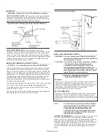
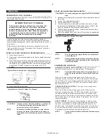
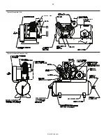
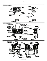
Typical Pressure Switch Lever (If Equipped)

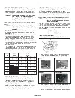
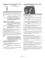
Typical Service Valve (A = Open, B = Closed)

A

B

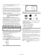
Typical Unloader (A = Unload, B = Load)

http://air.irco.com

Содержание 15T

Страница 1: ...ration and maintenance of your Ingersoll Rand air compressor Carefully read this manual before attempting to operate or perform any maintenance If you are uncertain about any of the instructions or procedures provided in this manual contact Ingersoll Rand We recommend you retain this manual and all publications provided with your air compressor in a location which is accessible to all personnel wh...

Страница 2: ...was damaged in transit reverts back to the claimant Read the unit nameplate to verify it is the model ordered and read the motor nameplate to verify it is compatible with your electrical conditions Make sure electrical enclosures and components are appropriate for the installation environment INSTALLATION SELECTING A LOCATION _____________________________ ELECTRIC MOTOR UNITS For most electric mot...

Страница 3: ...d tin soldered joints anywhere in the compressed air system CAUTION If you will be using synthetic compressor lubricant all downstream piping material and system components must be compatible Refer to the following material compatibility list If there are incompatible materials present in your system or if there are materials not included in the list contact Ingersoll Rand for recommendations SYNT...

Страница 4: ...2 6 8 30 0 1 6 8 MAGNETIC STARTER If the motor installed on your unit has a motor reset button it does not require a magnetic starter If the motor does not have this button and the unit does not have a factory installed starter install a magnetic starter with thermal overload protection Follow the manufacturer s instructions for installation Ingersoll Rand cannot accept responsibility for damages ...

Страница 5: ...o convert to All Season Select later on the pump must be decarbonized and flushed before conversion Contact Ingersoll Rand for more information FILLING PROCEDURES 1 Unscrew and remove the oil fill plug 2 Fill the crankcase with lubricant 3 Replace the oil fill plug HAND TIGHT ONLY CAUTION Do not remove the oil fill plug while the compressor is running Refer to the following table for crankcase cap...

Страница 6: ...the service valve and put the unloader lever in the unload A position for Kawasaki and Honda engine driven models or the load B position for Kohler engine driven models 5 Start the engine release the choke and allow the engine to warm up for two to three minutes 6 Return the unloader lever to the load B position on Kawasaki and Honda engine driven models NOTE Turn the gasoline supply off when the ...

Страница 7: ...H DIFFERENTIAL ADJUSTMENT CONTROL 1 Remove the pressure switch cover 2 Set the cut in pressure with the range adjustment nut Turn the nut clockwise in to increase the pressure or counter clockwise out to decrease the pressure NOTE One full turn changes the setting approximately 2 PSIG 3 Set the cut out pressure with the differential adjustment Turn the differential adjustment nut clockwise in to i...

Страница 8: ...f closed through the check valve therefore by passing the inlet unloader and escaping to atmosphere through the inlet filter silencer OIL CONSUMPTION CHECK___________________________ A rule of thumb in determining a passing grade for oil consumption is to consider consumption at or above 50 horsepower hours per ounce to be acceptable The formula is as follows Horsepower X Hours of Operation Horsep...

Страница 9: ...__ CHECKING BELT TENSION Check belt tension should be occasionally especially if looseness is suspected New belts must also be properly tensioned upon installation TENSIONING BELTS Belt tensioning can be achieved by loosening the motor or engine anchor screws pushing the motor or engine away from the pump and retightening the motor or engine anchor screws Some units are equipped with a belt tensio...

Страница 10: ...g 3 Remove the plug from the strainer with a suitable wrench If you hear air escaping from the cleaning port STOP IMMEDIATELY and repeat steps 1 and 2 4 Remove the stainless steel filter screen and clean it Remove any debris that may be in the strainer body before replacing the filter screen 5 Replace plug and tighten with wrench 6 When putting the EDV 2000 back into service press the TEST button ...

Страница 11: ...appearance in petroleum lubricant or rusting in cylinders 9 10 Motor overload trips or draws excessive current 5 6 12 13 14 15 16 19 20 21 34 Oil in discharge air oil pumping 4 7 9 18 19 25 35 Oil leaking from shaft seal 25 Safety relief valve pops 1 5 29 30 High interstage pressure 30 Low interstage pressure 31 Engine cranks slowly or will not start 6 14 37 38 Motor will not start 12 Engine will ...

Страница 12: ... rings not seated are stuck in grooves or end gaps not staggered Adjust piston rings 19 Cylinder s or piston s scratched worn or scored Repair or replace as required 20 Connecting rod piston pin or crankpin bearings worn or scored Loose bearing spacer on crankshaft Inspect all Repair or replace as required Install Bearing Connecting Rod Step Saver Kit 21 Defective ball bearings on crankshaft or mo...

Страница 13: ... IN 11 15 LB IN 11 15 LB IN 26 50 26 Low Pressure Outlet Valve Screws 25 30 LB IN 25 30 LB IN 25 30 LB IN 26 90 26 Beltwheel Bolt 33 60 60 113 213 213 High Pressure Head Center Bolts 10 Low Pressure Head Center Bolts 14 16 NOTE Tighten all fasteners evenly using a cross pattern in two stages MODEL DEFLECTION IN TENSION LB 2340 14 Span 0 25 4 9 7 1 2340 19 Span 0 29 4 9 7 1 2475 14 Span 0 25 4 9 7 ...

Страница 14: ... Motor Starter Coil OL Motor Starter Overload PS Pressure Switch SS Selector Switch Alternate wiring for converting 3 phase starter to 1 phase application if provided NOTE On units requiring a starter connect line power to the starter do not connect line power to the pressure switch l Connect ground wire to ground lug l L3 used for 3 phase motors starters only ELECTRICAL WIRING DIAGRAMS Single Pha...

Страница 15: ...15 Typical Baseplate Unit Typical Horizontal Simplex Unit http air irco com ...

Страница 16: ...16 Typical Duplex Unit Typical Gasoline Engine Unit Typical Vertical Simplex Unit http air irco com ...

Страница 17: ...s are expressly included the Company s obligation shall be to correct in the manner and for the period of time provided above THE COMPANY MAKES NO OTHER WARRANTY OF REPRESENTATION OF ANY KIND WHATSOEVER EXPRESSED OR IMPLIED EXCEPT THAT OF TITLE AND ALL IMPLIED WARRANTIES OF MERCHANTABILITY AND FITNESS FOR A PARTICULAR PURPOSE ARE HEREBY DISCLAIMED Correction by the Company of nonconformities wheth...

Отзывы: