background image

EonNAS 3000 Series Hardware Manual 

24 

1.3.6 

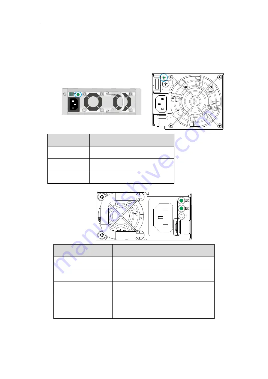
PSU LEDs 

The PSU LEDs are indicated by the 

blue circles

. Systems may have different PSU 

orientations. 


Item 

Description 

Flashing 

green


PSU is online but not powered on 

Steady 

green


Power on and status normal 

Red 

PSU failed 


LED 

Description 

AC off


DC off 

No power supplied 

AC 

green 

DC off 

AC power supply present 

AC 

green

 & DC 

green


DC power supply present 

Amber


Steady indicates PSU failure 

Flashing indicates PSU warning 

Содержание EonNAS 3000 series

Страница 1: ...Infortrend Hardware Manual EonNAS 3000 Series...

Страница 2: ...th Infortrend product Before installing any software applications or components provided by a third party customer should ensure that they are compatible and interoperable with Infortrend product by c...

Страница 3: ...A Tel 1 408 988 5088 Fax 1 408 988 6288 Email Technical Support Website US East Coast Office 4 Northeastern Blvd Suite 21B Nashua NH 03062 USA Tel 1 603 610 6398 Fax 1 603 610 6383 Email Technical Sup...

Страница 4: ...urthermore Infortrend Technology reserves the right to revise this publication and to make changes from time to time in the content hereof without obligation to notify any person of such revisions or...

Страница 5: ...er cables away from foot traffic Do not place items over power cords and make sure they do not rest against data cables Install all modules to the enclosure before powering on the system Should a modu...

Страница 6: ...Disconnect the power cords before servicing or cleaning the enclosure Use a slightly moistened paper sheet or cloth for cleaning Avoid using liquid or sprayed detergent When replacing components inse...

Страница 7: ...ad to discharge static electricity when installing or operating the enclosure Avoid dust debris carpets plastic vinyl and styrofoam in your work area Do not remove any module or component from its ant...

Страница 8: ...23 1 3 6 PSU LEDs 24 1 3 7 Cooling Module LED 25 1 4 System Monitoring Features 26 1 4 1 Monitoring 26 1 4 2 I2C bus 26 1 4 3 Audible Alarms 26 1 5 Hot Swapping 27 2 Hardware Installation 2 1 Before...

Страница 9: ...l Specifications 56 4 1 1 Hardware 56 4 1 2 Operating Environment 56 4 1 3 Power Supply 56 4 2 Certifications 57 4 2 1 Summary 57 5 Slide Rail Kit Installation Guide 5 1 Enclosure Installation Prerequ...

Страница 10: ...2011 Copyright and Contact update 1 3 Dec 2011 Added 3220 1 3230 1 3230 2 3230 3 models 1 4 Jan 2012 Added SSD installation instructions 1 5 May 2012 Updated memory upgrade installation Updated JBOD r...

Страница 11: ...based upon dedicated file service processing Ease of administration The ability to serve a common set of files to a heterogeneous client population Ease of installation High bandwidth connectivity on...

Страница 12: ...cters x 2 rows LCD panel and function keys allows you to view system events and configure the firmware Drive trays 2 Each drive tray is hot swappable and holds a 3 5 inch hard drive Handles 3 There ar...

Страница 13: ...Series Hardware Manual 13 1 1 2 Rear panel components Rear panel components comprise of power supply units 1 controller A 2 controller B 3 and dummy cage or expansion host ports 4 1 2 3 4 4 1 2 3 4 4...

Страница 14: ...s while a release button 2 can be used when retrieving disk drives from the chassis To the right of the bezel plate there is a drive busy LED 3 and a power status LED 4 No Item Description 1 Rotary be...

Страница 15: ...t connections and can be trunked 2 Serial Port The serial port is for maintenance purposes 3 USB ports The USB ports are for connecting to external devices 4 Host management port The host management p...

Страница 16: ...apply to selected models It is used for connecting to RAID storage devices Add on expansion connectivity ports For selected models with additional 1Gb iSCSI host ports For selected models with 10Gb i...

Страница 17: ...sual cues to system health The Service LED will light up in the event of controller power supply cooling fan failures or enclosure events that require maintenance services No Name Color Status 1 Servi...

Страница 18: ...the system is operating normally Amber indicates the system has encountered abnormal conditions 6 Power button N A Press and release instantly to turn on the system To force system to shutdown press...

Страница 19: ...l LEDs 1 3 1 Host Management Port LEDs 1 2 No Item Status 1 Speed LED Green indicates GbE connection established Off indicates 100Mb connection established 2 Link Status LED Amber indicates connection...

Страница 20: ...2 1Gb iSCSI Host Port LEDs 1 2 No Item Status 1 Speed LED Green indicates GbE connection established Off indicates 10 100 connection established 2 Link Status LED Amber indicates connection establish...

Страница 21: ...odels that come with 10Gbps iSCSI channel host ports The 10Gbps host connectivity is achieved by transferring data using iSCSI ports while data signals are sent through optical cables The 10Gbps iSCSI...

Страница 22: ...atus 1 Speed LED Green indicates 10Gb connection established Amber indicates 1Gb connection established Off indicates 10 100 connection established 2 Link Status LED Green indicates connection establi...

Страница 23: ...atus 1 Link Status LED Green indicates connection established Flashing green indicates data activity Off indicates connection not established 2 Speed LED Green indicates 16Gb connection established Ye...

Страница 24: ...orientations Item Description Flashing green PSU is online but not powered on Steady green Power on and status normal Red PSU failed LED Description AC off DC off No power supplied AC green DC off AC...

Страница 25: ...cooling module status LED lights up you will need to slide the enclosure out of the rack to look at the LED LED Status Description Off or green steady on Online and normal Red steady on Module failed...

Страница 26: ...es are reported through the in band methodology over the expansion links that is managed by a proprietary enclosure service 1 4 3 Audible Alarms The system comes with audible alarms that are triggered...

Страница 27: ...m the system when they are being replaced The following components are hot swappable PSU including cooling modules System cooling modules Hard drives NOTE Normalized airflow ensures sufficient cooling...

Страница 28: ...r can cause a down time 2 1 1 Hot swappable components Power supplies PSUs HDDs in drive trays RAID 5 configuration allows 1 hard drive to fail at any given time without data lost RAID 6 configuration...

Страница 29: ...1 Prerequisites Enclosure hard drive slot sequences Tray numbering sequence is important because if any faults occur to disk drives you should be able to identify the location of a faulty drive If you...

Страница 30: ...D arrays use a least common denominator approach meaning the maximum capacity used in each drive for comprising a logical configuration is the maximum capacity of the smallest drive Profile The enclos...

Страница 31: ...d With the connectors facing the open end of the tray secure the SSD to the tray refer to the blown up view below with a supplied flathead screw Once secured three other screw holes on the SSD will ma...

Страница 32: ...into the drive tray Make sure the hard drive is oriented that the drive s interface connector is facing the open side of the drive tray and its label side facing up Adjust the drive s location until t...

Страница 33: ...ray bezel opened gently insert the hard drive tray and the hard drive into the enclosure Once inserted into the enclosure close the tray bezel and use a small flat blade screwdriver to turn the bezel...

Страница 34: ...ing on procedures is also given in this chapter 2 3 1 Connection Concept The system connection concept is shown above where it connects to multiple client PCs and for the variant models they provide a...

Страница 35: ...re ID using the rotary switch on its LED panel Use a small size flathead screwdriver to change the ID NOTE Setting an identical ID on two JBODs will cause ID conflicts The enclosure ID determines the...

Страница 36: ...EonNAS 3000 Series Hardware Manual 36 Dual Controller dual SAS port JBOD expansion IN IN OUT OUT...

Страница 37: ...EonNAS 3000 Series Hardware Manual 37 Dual controller quadruple SAS port JBOD expansion IN IN OUT OUT IN IN ID 1 ID 3 ID 5 ID 7 ID 9 ID 11 ID 13 ID 2 ID 4 ID 6 ID 8 ID 10 ID 12 ID 14...

Страница 38: ...tly walked areas To ensure PSU redundancy please make sure that the two PSUs are plugged into two different power sources ie to different circuit breakers NOTE Make sure you use the power cables provi...

Страница 39: ...s etc and then turn on the NAS system by pressing the Power Button shown below in blue When turned on the service LED should remain off while the rest of the status LEDs on the front panel should ligh...

Страница 40: ...computer and you MUST turn off the firewall 1 Turning off Windows firewall To turn off the Windows firewall please refer to the instructions below Windows 7 Vista Click on the Start button Control Pan...

Страница 41: ...step 3 Please refer to the setup instructions in the User Manual on the CD 5 When the Set IP button lights up Click on it and EonOne will automatically assign an IP address for your NAS Wait for an IP...

Страница 42: ...nd click OK Mgmt0 Primary Ch0 Controller A Ch1 Controller A Ch2 Controller A Ch3 Controller A Mgmt0 Slave Ch0 Controller B Ch1 Controller B Ch2 Controller B Ch3 Controller B Interface DHCP DHCP DHCP D...

Страница 43: ...of configurations Click Back to modify the parameters or Apply to complete the Startup Wizard Press OK to initialize or to reboot when prompted Upon reboot a beep will sound to indicate successful sta...

Страница 44: ...al airflow will be disrupted Qualified engineers who are familiar with the system should be the only ones who make component replacements When inserting a removable module do not use excessive force F...

Страница 45: ...e controllers Please activate the controller if it is not Active Remove the screws underneath the controller levers and push down on both levers simultaneously to release the controller from the enclo...

Страница 46: ...ment If the server is mounted in a rack cabinet you will need to slide out the enclosure from the rack to replace the system cooling fans on the top of enclosure To extract the system fans To install...

Страница 47: ...onnect the power cord from the failed power supply Its LED should light static Red 2 Place your thumb around the side of the PSU ejection lever circled in red while hooking your index and middle finge...

Страница 48: ...he retention screw that secures the extraction handle to the chassis 3 To remove the PSU module pull the extraction handle downwards to disengage the PSU from the backplane connectors Once dislodged g...

Страница 49: ...replacement module Make sure the extraction handle is pointing outwards Push the replacement PSU into the chassis and when you feel the contact resistance push the extraction handle towards the PSU m...

Страница 50: ...ou purchase replacement or upgrade the module s please consult with your vendor on qualified components 3 4 1 Default and Upgrade DRAM Installation Slots Please install according to the following defa...

Страница 51: ...from your vendor WARNING Make sure both controller statuses are Active Remove ONLY one controller to upgrade at a time When reinserting the memory upgraded controller make sure the controller is Activ...

Страница 52: ...board to disperse 3 Remove the controller from the chassis please refer to Replacing the Controller 4 Push the clips outward on both sides of the DIMM slots and the DIMM module will eject automatical...

Страница 53: ...connectors 3 5 1 Detecting a Failed Hard Drive If a hard drive fails the system notifies you through the following indicators Audible alarm refer to Audible Alarms Hard drive tray status LED 3 5 2 Re...

Страница 54: ...ll the tray one inch away from the enclosure Wait for at least 30 seconds for the disk drive to spin down and then gently withdraw the drive tray from the chassis 5 Remove the retention screws Remembe...

Страница 55: ...ce thumbs on both sides 8 Lock the drive tray Turn the bezel lock to the vertical orientation locked position using a flat blade screwdriver Do not push the bezel lock while turning it otherwise the s...

Страница 56: ...HDDs 2 5 or 3 5 Onboard LAN 1x GbE Ethernet RJ 45 ports Cooling Hot swappable system fans PSU fans Mounting Rackmount rails for 19 rack cabinets 4 1 2 Operating Environment Temperature Operating 5 to...

Страница 57: ...B IEC 60950 1 2 nd Edition GOST R GOST R 60950 1 2005 EMC EN 55022 2006 A1 2007 EN 55024 1998 A1 2001 A2 2003 EN 61000 3 2 2006 A1 2009 A2 2009 EN 61000 3 3 2008 BSMI CNS 13438 FCC FCC Part 15 subpart...

Страница 58: ...check all components have been received against the Unpacking List Contact your vendor immediately if anything is missing Install the enclosure as is out of the packaging install hard drives and opti...

Страница 59: ...k cabinet 2 Enclosure onto the slide rail and into the cabinet 3 Hard drives into drive trays and then into the enclosure 4 Drive trays with or without hard drives into the enclosure 5 If Supercapacit...

Страница 60: ...the difference in bracket lengths has no effect on the installation procedure 5 2 1 IFT 9373 9CC 9N1 Kit Contents Item Description Quantity 01 Mounting bracket assembly L shaped Left side 1 02 Mountin...

Страница 61: ...e inner glides 03 to the left and right side of the enclosure using 6 32 L6 flathead screws 07 Make sure the protruding end indicated by the black arrow is bent inward as shown in the top view illustr...

Страница 62: ...sure Extend the rail to the appropriate length where it meets the rear post and secure the front and rear using M5x0 9mm screws 05 Slide runner indicated by the blue arrow and catch latch indicated by...

Страница 63: ...ch side filler plates come with the system 06 04 It is strongly recommended that two people perform this procedure together To mount the enclosure onto the rail and into the rack place the enclosure o...

Страница 64: ...ers manual and all hard drives have been removed It is strongly recommended that two people work together on this procedure 1 Remove the screws on the enclosure s ears shown above 2 Pull the enclosure...

Страница 65: ...rail kit 5 3 1 Kit Contents Item Description Quantity 01 Mounting bracket assembly left side 1 02 Mounting bracket assembly right side 1 03 Inner glides 2 04 Flathead screws 6 32 L4 6 05 Truss head s...

Страница 66: ...ns with determining the installation position front and rear rack positions and M5 cage nut 5 insertion location 3U M5 cage nut position Front rack posts Unit boundary Unit boundary 06 2U M5 cage nut...

Страница 67: ...ide to fix the length M5 x 9 0mm 05 M5 x 9 0mm 05 Inner glide rail 3 Attach inner glides to BOTH sides of the enclosure using flathead screws 6 32 8 6 32 08 4 With the assistance of another person lif...

Страница 68: ...tion Cease all input output transactions shutdown the system disconnect all the cables please refer to the User Manual for details Empty all drive bays hard drives hard drive trays and transport them...

Отзывы: