background image


10

SunLight Series UPS User Manual 


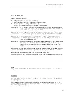
3.4.2   15-20-30  kVA 

 
The PK1 switch acts as follows: 
 

"0"


Off position (there is no Voltage at the UPS output) 

"1"

   Maintenance By-Pass (there is Line Voltage at the UPS output) 

"2"  

By-Pass  (there is Line Voltage at the UPS output) 

"3"

   Normal  (there is either Inverter or line Voltage at the UPS output) 


1. 

Position "0"  :  At  this  position ,  there is  no  AC  voltage  at  the UPS  output.  But  battery  charger   


  board  is  active  and  hence  the  batteries  are charged  if  battery  fuse and  AC  input   


  circuit  breaker  on  the front  panel  are closed. 


2. 

Position "1"  :  This is the "Maintenance By-Pass" position and at this position   the  load  is  supplied    


  by  AC  line   voltage. Again at this position , only   the  battery charger is in operation. 


3. 

Position "2"  :  At this position the load is supplied by AC line voltage through both  Maintenance  By- 


  pass and Static By-pass  acting  in  parallel   manner. Battery  charger and By-pass   


  drivers  are  in operation as well. 


4. 

Position "3"  :  When PK1 is turned to this position the Load is supplied  again by  line voltage at during  


  start-up and after a short delay  , inverter starts running,  (this  can  be seen by  

observing the cooling fans rotation) and the load is transferred  from  By-pass  to  
inverter. 


5. 

Disconnect  the input power. "LINE FAILURE"  will appear on the LCD panel  and  audible  alarm  will    


sound   intermittently.  Now the  load  is  supplied  from the  battery  source  through  the  inverter. 


6. 

Connect  the  power  again  and  see  that  "LINE  FAILURE"  alarm  is  off. 


7. 

Now  your  UPS  is  ready  to  operate. Connect  the  critical  loads to  the output terminals of the unit. 


NOTE 

If any condition is different from the above situation, call our local service representative for assistance. 


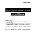
CAUTION ! 

 
After initial start-up, keep power continuously to the unit for at least 12 hours to ensure that the batteries 
are fully charged.  
 
During battery charging, the inverter can be shut down by turning the On-Off Switch PK1 to " off - 0 " 
position.  In this case the main switch should be kept in " on-1 " position and it must be kept in mind that 
there is line voltage at the output.   


Содержание SunLight -210

Страница 1: ...USER MANUAL UNINTERRUPTIBLE POWER SUPPLIES 3 Phase Input 1 Phase Output info rise TECHNOLOGIES SunLight 206 6 kVA SunLight 207 7 5 kVA SunLight 210 10 kVA SunLight 215 15 kVA SunLight 220 20 kVA SunL...

Страница 2: ...edure 11 4 2 2 Turn Off Procedure 11 4 3 When Utility Power Is Interrupted 11 4 4 Operator Control Panel 12 4 4 1 Push Buttons 12 4 4 2 First Message Line Of The LCD 12 4 4 3 Second M L ALARMS Of The...

Страница 3: ...ified service personnel The output may be energized when the unit is not connected to a mains supply Risk of electric shock hazardous live parts inside this unit are energized from the battery supply...

Страница 4: ...and maintenance by pass LCD Liquid Crystal Display display Alarm history Memory for max 64 alarms Automatic battery testing optional High quality maintenance free lead acid type batteries High nonline...

Страница 5: ...ransfer Switch static by pass Static transfer switch is an electronically controlled switching circuit checked by main controller board In case of inverter overload or any other faults STS transfers t...

Страница 6: ...Frequency 50 Hz Line Synchronized 1 Output Frequency Tolerance Free Running 0 2 Efficiency 100 Load 85 87 Crest Factor 3 1 Overload capacity 100 125 Load 2 5 min 125 150 Load 10 sec 150 instant by pa...

Страница 7: ...ections Battery Fuse AC Output 220V AC 50Hz 10A max DB9 Port PK1 On Off Switch Main Switch Figure 2 2 1 6 7 5 10 kVA Rear view Figure 2 2 2 Front views Main Switch PK1 On Off Switch UPS Electrical Con...

Страница 8: ...ocation Selection The UPS is designed to be installed in a protected environment The following conditions should be prohibited 1 Blocking the airflow intake and outlet It is recommended to retain 10 c...

Страница 9: ...ioned and secured connect the power cables as described in the following section It is recommended that the UPS should be connected to the line voltage protected by a circuit breaker 1 Before connecti...

Страница 10: ...give the inverter power to the output 3 Disconnect the input power The LINE FAILURE indicator will be on and audible alarm will sound intermittently Now the output receptacles are supplied from the ba...

Страница 11: ...ion as well 4 Position 3 When PK1 is turned to this position the Load is supplied again by line voltage at during start up and after a short delay inverter starts running this can be seen by observing...

Страница 12: ...wer cords into outlets 4 2 15 20 30 kVA 4 2 1 Turn On Procedure 1 Turn On Main Switch PK1 on the front panel from position 0 to 3 step by step as in the instructions given in chapter 3 4 2 2 Turn on t...

Страница 13: ...onal sections LED indications and control and display As can be seen the upper section consists of leds which indicate the operation mode This panel shows the systems operation such as input and outpu...

Страница 14: ...LINE MODE UPS operating mode LINE FAILURE You have no AC input at the UPS input BATTERY TEST Performing battery test BAT AUTONOMY END Battery autonomy has finished BATTERY LOW UPS battery voltage is b...

Страница 15: ...g the batteries FAULT 7 Rectifier fault Please call service for checking the UPS FAULT 8 Line voltage out of tolerance 4 5 Automatic battery test system optional There are some conditions to make this...

Страница 16: ...oftware the UPS and the computer system communicate so that the computer system is warned of impending UPS shutdown Software RUPS RUPSII UPSILON SNMP devices is available for most operating systems an...

Страница 17: ...d to your network through SNMPVIEW Software supplied with the module or it is possible to monitor the UPS through an Internet Browser It is possible to shutdown the servers or users with Client mate S...

Страница 18: ...PS system from several different locations at the same time 5 5 UPS Port Sharer Multiple server shut down unit Using one of this units you can automatic shut down of 4 8 servers or PC where without LA...

Страница 19: ...18 SunLight Series UPS User Manual...

Страница 20: ...19 SunLight Series UPS User Manual Connection Diagram Of The RMP COM1...

Страница 21: ...persistent failure or problem properly turn off the unit first Then review the following check list Be prepared to answer the questions before calling the service 1 Did you follow the operation proced...

Страница 22: ...not apply if the product has been subjected to physical abuse improper installation unauthorized service or modification 2 The sole responsibility of corporation under this warranty shall be limited...

Отзывы: