


Application Note
23 of 36
002-34970 Rev. **
2022-05-03
Foreign object detection tuning guide for wireless power transmitters
Applicable for WLC ICs
FOD parameter tuning
3.5.2
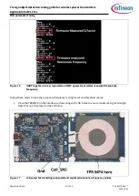
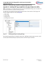
Resonance frequency-based FOD tuning
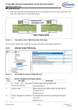
Figure 19
View of Q factor settings configuration tool
Table 3
Resonance frquency Q factor configuration setting parameters
S. no.
Parameter
Description
1
Resonance frequency measurement
threshold ( x0.1% )
Resonance frequency measurement threshold in
percentage. x0.1% scale.
Default value is 67.
2
Resonance frequency scale factor
(x0.1% )
Resonance frequency measurement threshold in
percentage. x0.1% scale.
Default value is 856.
3.6
System power loss curve coefficient tuning
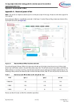
A Qi-compliant power transmitter has three modes of operation:
•
EPP15: Illustrated with TPR#MP3
•
EPP5W: Illustrated with TPR#7
•
BPP: Illustrated with TPR#5
This section covers tuning FOD functionality parameters for all three modes of operation.
System power loss curve coefficient tuning
requires a tuning setup based on the user. Refer to the WPC
member login page for details of the list of WPC-approved compliance testers. Refer to section
required tools and section
for details on setting up the hardware. Refer to the WPC member login page for
details of the list of WPC-approved compliance tester-based experimental setups required for this tuning
process.
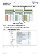
3.6.1
Data collection and system loss curve coefficient calculation
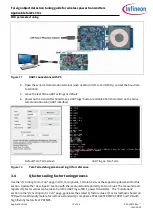
1.
Enter the Advanced mode on the compliance tester tool user interface.
2.
Connect TPR#MP3 to the compliance tester. Refer to the WPC member login page for details of the list
of compliance tester tools and place it on the interface surface of the transmitter.
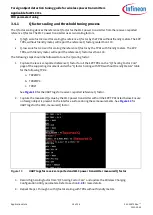
3.
Select
Current
load
in the
Power load
tab. (Default is Resistive load).
4.
Ensure the best alignment between the transmitter and receiver coils. Refer to