


XC2200 Derivatives
System Units (Vol. 1 of 2)
System Control Unit (SCU)
User’s Manual
6-74
V2.1, 2008-08
SCU, V1.13
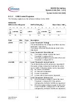
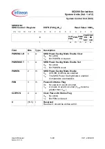
6.4.1.7
Pad Configuration for ESR Pads
The configuration is selected via bit field ESRCFGx.PC.
The pad functionality control can be configured independently for each pin, comprising:
•
A selection of the driver type (open-drain or push-pull)
•
An enable function for the output driver (input and/or output capability)
•
An enable function for the pull-up/down resistance
The following table defines the coding of the bit fields PC in registers ESRCFG0,
ESRCFG1, and ESRCFG2.
Note: The coding is the same as for the port register bit fields Pn_IOCRx.PC.
Table 6-9
PC Coding
PCx[3:0]
Selected Pull-up/Pull-down /
Selected Output Function
I/O
Output
Characteristics
0000
B
No pull device activated
Input is not inverted,
the input stage is
active in power-down
mode
0001
B
Pull-down device activated
0010
B
Pull-up device activated
0011
B
No pull device activated
0100
B
No pull device activated
Input is inverted,
the input stage is
active in power-down
mode
0101
B
Pull-down device activated
0110
B
Pull-up device activated
0111
B
No pull device activated
1000
B
Output of ESRCFGx.OUT
Output,
the input stage is not
inverted and active in
power-down mode
Push-pull
1001
B
Output of ESRCFGx.OUT
1010
B
Output drives a 0 for an Internal
Application Reset, a 1 otherwise.
1011
B
Output drives a 0 for an
Application Reset, a 1 otherwise.
1100
B
Output of ESRCFGx.OUT
Open-drain,
a pull-up device
is activated
while the output
is not driving a 0
1101
B
Output of ESRCFGx.OUT
1110
B
Output drives a 0 for an Internal
Application Reset
1111
B
Output drives a 0 for an
Application Reset


