System
description
[email protected] | www.romanoff.com
2019-10-16
4
–2
4.2
Schematic representation
Figure 1: overall view
1
3
4
5
6
2
7
Position Description
Function
1
tilting handle with
lock
Due to movement to the right the machine will
cast.
2
inductor housing The melting and casting process takes place
here.
3
control buttons.
Control the casting process. See ch. 4.6.
4
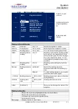
LCD screen
See chapter 4.5
5
top plate with
handle
Locks the inductor housing.
6
lock
Locks the system for safety reasons and to
allow overpressure.
7
mains switch
Machine will be turned on and off here.

