Man-AIM-AUS
Issue 01
October 2011
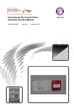
Conventional Fire Control Panel
AFP-2516
Australian Interface Module
Страница 1: ...Man AIM AUS Issue 01 October 2011 Conventional Fire Control Panel AFP 2516 Australian Interface Module ...
Страница 2: ...ard 5 5 24V Input 6 6 Connection to main panel and other boards 6 7 Operation 8 7 1 Normal condition 8 7 2 ACF Ancillary Control Facility 8 7 2 1 Outputs 8 7 2 2 Configuration 8 7 2 3 Controls only available at Access Level 2 8 7 3 Door Holder Output 8 7 4 ASE Outputs Alarm Signalling Equipment 9 7 5 Fuse fail 9 7 6 COMMS 9 7 7 Microprocessor Reset link 9 7 8 Module Address 9 8 Power requirements ...
Страница 3: ...ce ASE from the control panel via a 2 core data bus The Australian Interface Module is compatible with all Sigma CP control panels Only one AIM is permitted on each control panel and has a fixed addressed at o7 output unit 7 NOTE The Australian Interface Module if fitted is fixed at address 7 and in this instance only 6 Ancillary boards can be fitted at addresses 1 to 6 The total length of the dat...
Страница 4: ...make any appropriate information about this product available to anyone concerned with its use This Ancillary board is designed for indoor use only and at temperatures between 50 C and 400 C and with a maximum relative humidity of 95 The IP rating for the enclosure is IP30 Operation outside of these limits may render the equipment unreliable and unsafe 2 2 Mounting If not fitted inside a Sigma CP ...
Страница 5: ...Maximum total cable distance 1200 metres Metal cable glands should be used Size 155 X 135 X 30 Millimetres Fixing Four 4mm holes One in each corner of the board 4 Connecting to the circuit board All connections for field wiring are to rows of terminals along the top and bottom of the circuit board Cabling must comply with the relevant Australian Standards Shielded fire alarm cable for power and RS...
Страница 6: ...ient Four power terminals are provided so that 24V DC wiring can be taken into the module and then out again on to other ancillary boards or other equipment 6 Connection to main panel and other boards If power is supplied locally to the Australian Interface Module board only two wires are required from the main panel Wiring can be standard fire alarm cable or shielded data cable The shield of the ...
Страница 7: ...et switch on the main panel PCB The main panel will display the address of the first board it finds on the seven segment LED display such as o1 This indicates ancillary board 1 o1 To accept this the enter button on the main panel should be pressed whereupon if more boards are found their addresses will be displayed and must be accepted by pressing the enter button once again This is repeated until...
Страница 8: ...IM module in order to reset the ACF firstly the Alarm must be reset and then the ACF can be reset using the ACF Reset switch on the AIM module When the ACF is set to non latching the ACF output is deactivated when the alarm is reset or disabled The Isolate switch on the AIM module allows the ACF output to be disabled and not operate on an alarm condition A yellow ACF Isolated LED indicates when th...
Страница 9: ...ored output If voltages or currents exceeding those in Table 1 on Page 5 need to be switched then a suitable relay or contactor device should be interposed between the ancillary board and the system to be controlled 7 5 Fuse fail The AIM is fitted with a 1 Amp rated self resetting electronic fuse This fuse protects the electronics of the AIM and prevents any excessive loading of the power supply t...
Страница 10: ...Sigma_CP_Australian Interface Module doc Page 10 of 10 When supplied from the Sigma CP panel extra battery capacity of 0 6Ah should be allowed to give 24 Hour standby ...