


Incite Hochiki-Securiton Interface Module– Rev 1.0
Page 5 of 21
3
Operation:
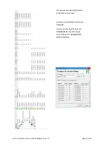
The state of the ASD outputs are detected by the main interface module (SEC-HIM-35) and
transmitted back to the FIP via the CHQ-POM and the Hochiki Loop. These are then available for
processing via the FIP. The ASD reset is achieved by toggling the CHQ-POM output for 5 seconds,
which in turn is fed into the ASD Reset input.
On the SECRDU, the LEDs are controlled, and the Disable and Reset touch buttons are processed via
Cause and Effect equations in the Syncro or Taktis FIP.
3.1
Alarm:
When the first alarm contact closes on the ASD, the resistor network on the SEC-HIM-35 sets an
alarm on the CHQ-POM input 1. This is then detected by the FIP and processed as per the settings in
the FIP configuration.
Similarly, when a second detector head is used in the ASD535, the second alarm contact sets an
alarm on the CHQ-SIM located on the SEC-HIM-35B module.
3.2
Fault Mode:
All the inputs on the SEC-HIM-35 and SEC-HIM-35B are monitored for open circuit and short circuit
faults. Should any portion of the unit be unplugged, a fault will be generated.
When the fault contact on the ASD is activated, the second input on the CHQ-POM is activated. This
allows the input to signal a fault and also trigger other devices through C&E if needed.
3.3
Controls:
The control buttons on the SECRDU are capsense type. They are activated by placing a finger onto
the faceplate, where the finger capacitance is detected by the PCB circuitry. A buzzer will beep
whenever a finger is detected.
3.3.1
Reset:
This button has a momentary function. Activating this button will place a 5 second reset pulse n the
connected ASD unit. If the alarm is still present on the ASD, it will have no effect.
3.3.2
Disable:
This button has a toggle operation. Activating this button will disable the Alarm and Fault inputs
from the ASD. If required, the FIP C&E can be used to turn off the ASD when this button is activated
by holding the reset signal on the ASD.