background image

iOKE868 LoRaWAN® / 

 / 

User Manual Version: 1.0

Page 7 of 12

iO881A Startup

After a power cycle or reset the iO881A performs a startup procedure which includes the following steps:

Step 1: System Startup & Module Configuration
After successful system startup the iO881A reads and validates the required configuration settings. In case of valid settings the
following hardware and firmware modules will be configured:

RTC with time-stamp from NVM, stored during last synchronization via PC or LoRaWAN  network

®

LoRaWAN  Stack

®

OBIS-ID Filter
Event Calendar

In case of missing LoRaWAN  settings the iO881A enters a sleep mode and waits for further configuration (

).

®

Step 2

Every LoRaWAN® device must be activated at least once before usage. If not already activated, the iO881A enters sleep mode and
waits for a HCI message from a PC-Tool to start the LoRaWAN® activation procedure (

). 

Step 3

Step 2: iO881A Configuration
The initial configuration must be handled via serial connection and PC-Tool. During configuration phase several parameters for

LoRaWAN  activation, Calender Events and OBIS-ID Filter have to be set to change the iO881A behavior.

®

Note: the LoRaWAN  Stack can be deactivated and reactivated again.

®

Step 3: LoRaWAN Stack Activation (OTAA or ABP)

®

In case of Over The Air Activation (

) the iO881A initates the LoRaWAN  join procedure. On success the device continues with

OTAA

®

the next step. The join procedure and its final result will be signalized via 

. If Activation By Personalization (

) is selected the

LED

ABP

LoRaWAN  Stack will be activated and the next step is directly initiated.

®

Step 4: Real Time Clock Synchronization

For proper calendar operation the iO881A requests the LoRaWAN  network time and synchronizes the internal real time clock

®

(RTC). At first the time will be requested by means of a LoRaWAN MAC command. In case of no MAC response, a defined
application command is used to retrieve the current date and time from the application server ( refer also to 

Real Time Clock

 ). 

Synchronization

Step 5: Time Correction of Calendar
In this final step the calendar unit is updated to handle the configured events which control the subsequent application behavior.

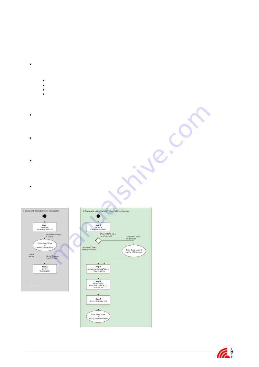
The following flow chart outlines the iO881A startup procedure and it's single steps.

Figure : iO881A startup with invalid & valid configuration

Содержание 404620

Страница 1: ...MST GmbH Carl Friedrich Gau Str 2 4 D 47475 Kamp Lintfort iOKE868 LoRaWAN User Manual Version 1 0 Document State initial Date October 2020 Document ID 4000 40140 160 2020 IMST GmbH All rights reserved...

Страница 2: ...f 12 History Version Date Comment 1 0 October 2020 Initial Version Content General User Information Hardware Overview iO881A Startup Reader Functions Real Time Clock Synchronization LED and Push Butto...

Страница 3: ...explicit nor implicit is given for the correctness at the time of publication IMST GmbH reserves all rights to make corrections modifications enhancements and other changes to its products and servic...

Страница 4: ...s do so at their own risk Any resale of IMST GmbH products or services with statements different from or beyond the parameters stated by IMST GmbH for that product solution or service is not allowed a...

Страница 5: ...an overview about the hardware of iOKE868 iOKE868 LoRaWAN consist of iO881A for LoRaWAN antenna micro USB cable Figure iO881A for LoRaWAN antenna and USB cable Features of iO881A USB interface for gen...

Страница 6: ...cult RF environments Power Supply The iO881A is supplied via the Micro USB interface The configured iO881A can be supplied by an additional USB power supply or battery pack Interfaces of iO881A Push b...

Страница 7: ...alender Events and OBIS ID Filter have to be set to change the iO881A behavior Note the LoRaWAN Stack can be deactivated and reactivated again Step 3 LoRaWAN Stack Activation OTAA or ABP In case of Ov...

Страница 8: ...ement value within this record The OBIS ID Scan Mode can be activated to read and forward only the published OBIS IDs of the connected meter The captured OBIS IDs will be sent as a list via wired loca...

Страница 9: ...value is used to configure the RTC and is finally stored in the NVM for later usage after a system reset Due to the fact that some LoRaWAN server do not support the Get Time MAC Command a fall back m...

Страница 10: ...en 1 x Not used LoRaWAN stack activated Nothing iO881A is ready for meter data reading Red 2 x Read error or no data LoRaWAN configuration invalid or not activated Connect iO881A to PC and start confi...

Страница 11: ...equires an initial configuration before usage This configuration can be done by means of a PC Tool called WS Configurator which is connected via serial interface USB to the device For further informat...

Страница 12: ...Antenna Via MMCX connector LoRa Protocol Characteristics LoRaWAN Certified and compliant to V 1 0 2 Activation type ABP activation by personalization OTAA over the air activation Frequencies Standard...

Отзывы: