15
462
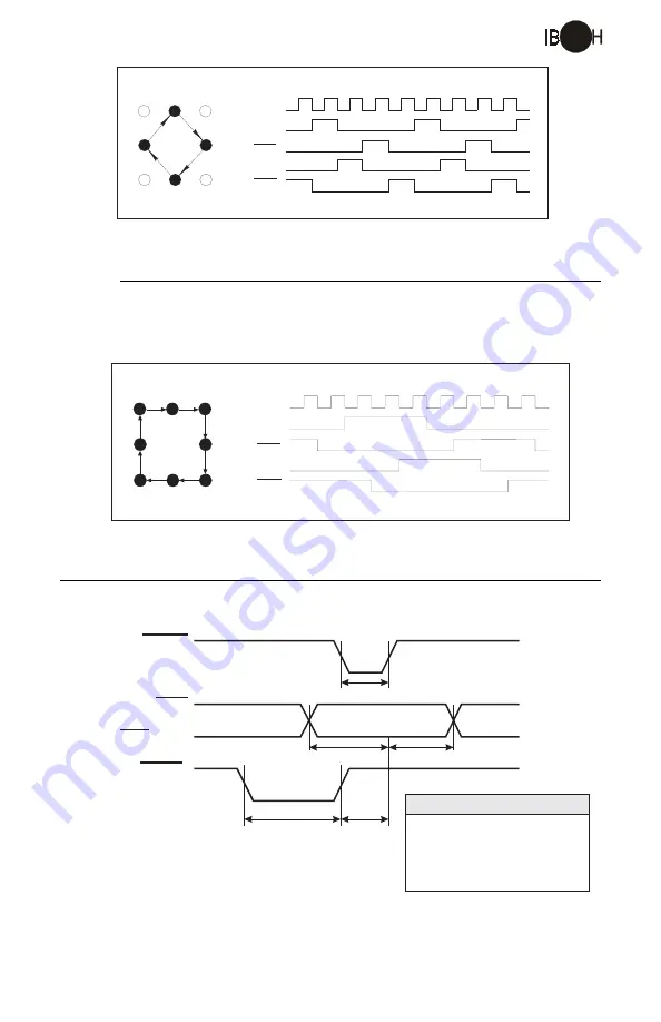
Figure 1.4.3: Wave Mode Phase Sequence
H a l f S t e p M o d e
In half step mode the phasing alternates from one phase energized to two phases
energized. Half step mode is selected by a high on the Half/Full Step input.
Figure 1.4.5: Timing Diagram
1
3
5
7
2
4
6
8
2
4
6
8
2
4
6
8
2
STEP CLOCK
PHASE A
PHASE B
PHASE A
PHASE B
1
3
5
7
2
4
6
8
1
2
3
4
5
6
7
8
1
STEP CLOCK
PHASE A
PHASE B
PHASE A
PHASE B
Figure 1.4.3: Half Step Mode Phase Sequence
T i m i n g
t
CLK
t
S
t
H
t
R
t
RCLK
CLOCK
CW/CCW
HALF/FULL STEP
RESET
Parameter
Minimum
t
- Clock Time.......................0.5µs
t
- Set up time..............................1µs
t - Hold Time.................................4µs
CL C
K
S
H
t
- Reset to Clock Delay...........3µs
t - Reset Time...............................1µs
RLCK
R


