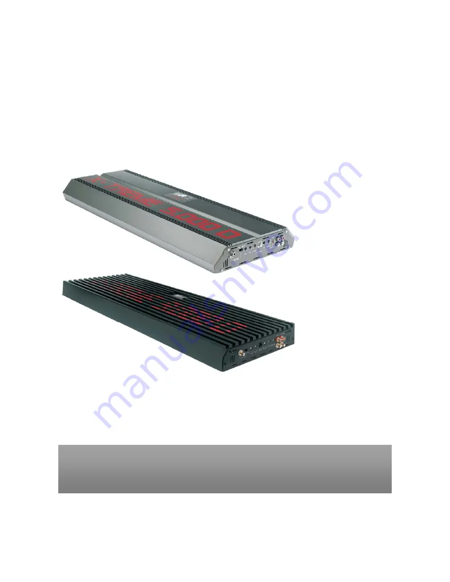
X TREME POWER
CLASS D AMPLIFIER
AMPLIFIER
Owners Manual
XT 3.5KW, XT 5.0KW, XT 9.0KW
Страница 1: ...X TREME POWER CLASS D AMPLIFIER AMPLIFIER Owners Manual XT 3 5KW XT 5 0KW XT 9 0KW ...
Страница 2: ...oncert levels of sound pressure Continued exposure to excessively high volume sound levels will cause hearing loss or damage Also operation of a motor vehicle while listening to audio equipment at high volume levels may impair your ability to hear external sounds such as horns warning signals or emergency vehicles thus creating a potential traffic hazard In the interest of safety We highly recomme...
Страница 3: ...brake lines oil lines and electrical cables when planning the install Make sure there is at least 2 inches 5 cm around the air vents on the amplifier When connecting ground points make sure all paint is carefully scrapped away from the auto body and contact is make with bare metal Use a utility knife to trim away fabric from hole locations before drilling or cutting When running power cables throu...
Страница 4: ...and installation is completed CONTROL PANEL LAYOUT Fig 1 Panel Layout XT 3 5KW XT 5 0KW Fig 1 Panel Layout XT 9 0KW 3 ...
Страница 5: ...EQ Control This equalization circuit is used to enhance the low frequency response of the vehicle s interior With up to 18dB of boost centered at 45 Hz the BASS EQ can be adjusted to meet your own personal taste 6 BASS REMOTE Jack This is the connector port for the Remote Bass Control When using this control set the BASS EQ control 5 to the maximum 18 dB position Now the amplifiers low frequency e...
Страница 6: ...s terminal This can be found on the rear of the source unit in the form of an electric antenna output or a remote output If this is not available you can wire to the ACC position on the key A 1 mm2 wire is sufficient to run the REMOTE 16 SPEAKER Terminals As shown in the wiring diagrams be sure to observe speaker polarity through the system and speaker impedance This specially tooled terminal is d...
Страница 7: ...ps etc Power Input Connections Fig 2 Panel Input Connection XT 3 5KW XT 5 0KW Fig 2 Panel Input Connection XT 9 0KW This amplifier is designed to work within a 10 to 16 8 Volt DC range Before any wires are connected the vehicles electrical system should be checked for correct voltage supply with the help of a voltmeter First check the voltage at the battery with the ignition in the OFF position Th...
Страница 8: ...sh or sandpaper to eliminate unwanted paint for better contact of the ground Secure the ground cable to the body using a bolt star washer and nut Spread silicon over the screw and bare metal to prevent rust and possible water leaks Now it s time to connect the power and ground cables to the amplifier Cut both cables to length Strip off inch 12mm of the insulation so that the bare wire fits all the...
Страница 9: ...ire to length Loosen the screw terminal marked REMOTE on the amplifier using a Philips cross type screwdriver Insert the stripped bare portion of the wire into the terminal and tighten the screw securely RCA Interconnects Fig 3 Low Level Input using RCA XT 3 5KW XT 5 0KW 8 ...
Страница 10: ... side of the vehicle and that they do no cross each other this will help reduce any noise that may radiate from the power cable and the signal cable If an audio cable is too close to a power cable it may pick up the magnetic field generated by the power cable which could lead to a loss of quality in your signal Bass EQ Remote Controller Connection Fig 4 Connection with RJ45 Jack Your X Treme D Cla...
Страница 11: ...Fig 5 A Single Voice Coil Subwoofer 1 4 ohm XT 3 5KW XT 5 0KW Fig 5 A Single Voice Coil Subwoofer 1 4 ohm XT 9 0KW Fig 6 A Single Voice Coil Subwoofer 1 4 ohm XT 3 5KW XT 5 0KW 10 ...
Страница 12: ...or by soldering the connection to the speaker Be certain to maintain correct polarity throughout the system Make sure the speaker connections are positive to positive and negative to negative Most speaker wire has some indicator color code ribbing or printing on one of the two wires to help you distinguish the positive and negative leads At the amplifier end insert the stripped bare speaker wires ...
Страница 13: ...p to 18dB Keep in mind that more is not always better Setting the control to the max 18dB will stress the amplifier and the speakers and could result in damage Fig 9 Low Pass Control Low Pass Filter LPF Adjustment The crossover frequency adjustment filters out frequencies that you don t want your speaker s to reproduce Using the LPF control adjust the Low Pass Frequency to limit the amount of mid ...
Страница 14: ... Sonic Filter Adjustment This filter avoids the reproduction of inaudible low frequencies which could damage the subwoofer s The Sub Sonic filter is fully adjustable between 20Hz and 50Hz Frequencies below 20 Hz are considered inaudible to the human ear HOW TO SET UP 1 A SINGLE VOICE COIL SUBWOOFER SPEAKER XT 3 5KW XT 5 0KW Don t connect two 1 Ohm speaker simultaneously 1 A SINGLE VOICE COIL SUBWO...
Страница 15: ... XT 3 5KW XT 5 0KW Note Don t connect speaker impedance under 2 ohms 2 TWO SINGLE VOICE COIL SUBWOOFER SPEAKERS XT 9 0KW Note Don t connect speaker impedance under 2 ohms 3 MONO BLOCK INSTALLATION FOR DAISY CHAIN XT 3 5KW XT 5 0KW Main Unit 14 ...
Страница 16: ...etween the speaker terminals of the two amplifiers and use speaker wiring Install a wire link between the speaker terminals of the two amplifiers If this is not done the system will not function properly and damage to the amplifiers may result Total impedance of speakers must be over 2 ohms If the impedance drops under 2 ohms critical damage to the amplifier will occur 15 ...
Страница 17: ...the Voltage protection engaged Voltage to the amp is vehicle is running not within the 10 15 VDC operating range Have the battery charging system inspected 3 Amp plays at very low volume Short circuit protection is engaged Check for speaker wires shorted to each other or the vehicle chassis Speakers operating below the minimum impedance an cause this to occur Alternator noise varies with RPM Check...
Страница 18: ...0W x 1 or 2 500W x 2 9 300W Signal to Noise Ratio 80dB 90dB Frequency Response 10Hz 500Hz 1dB 15Hz 400Hz 3dB Crossover Low Pass Filter 50Hz 450Hz 50Hz 400Hz Crossover Slope 24dB Octave Sub Sonic Filter 20Hz 50Hz Bass EQ at 45Hz 0 18dB Input Gain Control 0 2V 6 0V Low Level Input Impedance 22K Ohms Damping Factor 300 into 4 Ohms 213 into 4 Ohms Dimensions Width W x 265mm 324mm Height H x 63mm 65 5m...