54
CHAPTER 10: CAN COMMUNICATIONS
NOTE:
For additional CAN information, refer to the CAN Networks manual on the IMO website.
10.1 Overview
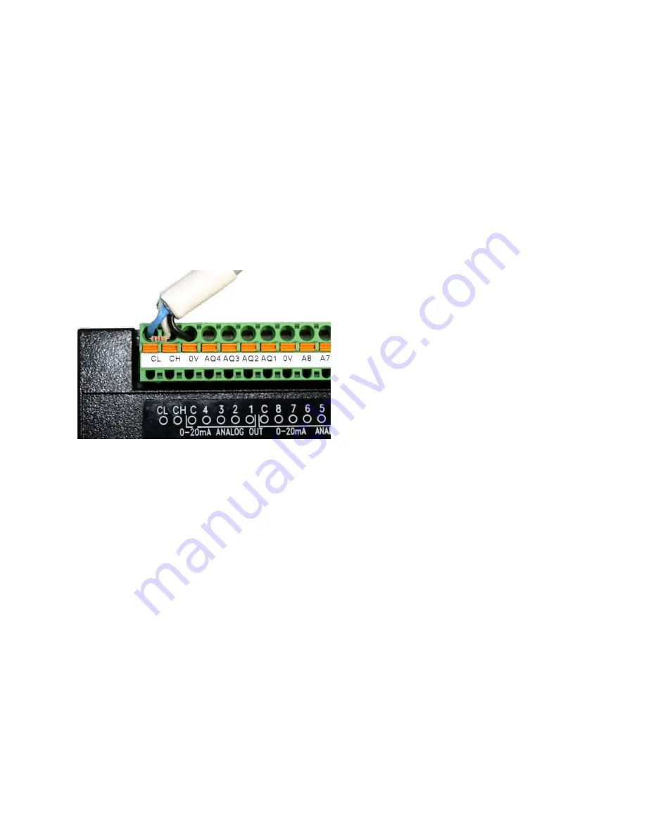
All I3N models provide CAN networking options, which are implemented with
CL
and
CH
connections at
the terminal. They are like the module shown below. The CAN connection is terminated (120
Ω
resistor)
at each end of the network wiring for proper functionality.
NOTE:
The order of the CL and CH connections differ depending on the I3N model being used. Please refer
to the datasheet for the specific I3N being used.
Figure 10.1 – CAN Connection
The CAN port can be used for I3N programming by connecting it to the CAN port of another I3 or I3N that
is connected with i3 configurator. The CAN port also allows the I3N to exchange global data with other
i3/RCS controllers. CAN supports accessing of remote network I/O devices.
10.2 Port Description
The I3N CAN ports implement the ISO 11898-2 physical layer and the CAN 2.0A data link layer standards.
Also, since the CAN ports are powered by an internal isolated power supply, external CAN power is not
required for the I3N CAN port itself. However, external CAN port power is required for remote I/O devices.
Содержание i3N Series
Страница 1: ...Think inside the box User Manual For i3 N Series Controllers...
Страница 39: ...39...


