Immergas Victrix Maior 28 TT 1 ErP Скачать руководство пользователя страница 30

30

INS

TALLER

US

ER

MAINTEN

AN

CE TECHNI

CI

AN

3.

7

  CALIBRATION TYPE INVOLVING 

THE REPLACEMENT OF A 

COMPONENT.

When performing extraordinary maintenance 

on the boiler, involving the replacement of a 

component, such as the P.C.B. (if the removable 

memory is not put into the replacement board) 

or components in the air, gas and flame control 

circuits, the boiler will need to be calibrated.

Select the type of calibration to be carried out 

according to the table below.

Replaced 

component

Type of calibration 

required

Gas valve

Q

uick calibration

Fan

Q

uick calibration

Burner

Complete calibra-

tion with air-gas ratio 

check

Ignition/detection 

electrodes

Complete calibra-

tion with air-gas ratio 

check

P.C.B. 

(New virgin P.C.B. 

without removable 

memory recovery) 

Restore the param-

eters as described in 

the paragraph "P.C.B. 

programming"

Complete calibra-

tion with air-gas ratio 

check

P.C.B.

(Recovery of the 

removable memory 

with the boiler 

parameters set from 

the replaced board)

No calibration re-

quired.

3.8  COMPLETE CALIBRATION 

FUNCTION.

N.B.:

 before carrying out complete calibration, 

ensure that all the requirements indicated in 

paragraphs 1.23 and 1.24 have been fulfilled.

IMPORTANT NOTE:

 to access this function 

it is crucial that there are no active requests for 

central heating or DHW production.

In the event of anomaly “62” or “72” (see parag. 

2.5) the boiler cancels any requests by itself.

N.B.:

 during the various calibration stages, the 

air - gas ratio can be checked and possibly cor-

rected as described in par. 3.9.
The energy produced is dissipated via the heat-

ing circuit; alternatively, the energy can be 

released from the DHW circuit by opening any 

hot water tap.

Caution:

 in this case the only active temperature 

control is the flow probe that limits the maximum 

temperature exiting the boiler at 90°C, therefore 

be careful not to get burned.
- The calibration procedure involves various 

stages:

  - nominal heat output calibration;
  -  intermediate heat output ignition calibration;
  - minimum heat output calibration;
  - calibration self-check.
Each calibration procedure, if carried out without 

altering the parameters, lasts 5 minutes at the 

most, after which it switches automatically to 

the next parameter until the calibration process 

is complete.

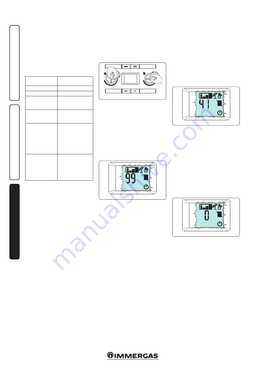
In order to access the complete calibration 

stage, you must switch the boiler on, set the 

DHW selector in the “6 o' clock” position and 

the heating selector in the “9 o' clock” position, 

(Fig. 3-5) and press the “Reset” button for about 

8 seconds until the “chimney sweep” function 

is activated; then press the “summer / winter” 

button within 3 seconds.


Nominal heat output:

 with the function active, 

the boiler carries out the procedures required 

to calibrate the appliance at the nominal heat 

output.

  At this stage the display features flashing 

icons: “summer”, “winter”, “stand-by” and the 

operating temperature alternated with the 

current operating heat output (99%); once the 

parameters are detected and stabilised, the 

frame of the flame presence symbol (ref. 10 fig. 

2-1) will start flashing (this procedure may last 

a few minutes), meaning that the nominal heat 

output parameters have been set.

  The air - gas ratio can only be corrected after 

the flame presence frame has flashed (see parag. 

3.9) or switch to the next heat output parameter 

by pressing the “info” button.

3-5

3-6


Intermediate heat output ignition:

 once the 

nominal heat output calibration is confirmed, 

the boiler is calibrated with the intermediate 

heat output (or ignition heat output).

  At this stage the display features flashing 

icons: “summer”, “winter”, “stand-by” and the 

operating temperature alternated with the cur-

rent operating heat output (typically 41% but 

variable according to the boiler model); once 

the parameters are detected and stabilised, the 

frame of the flame presence symbol will start 

flashing, meaning that the intermediate heat 

output parameters have been set.


The air - gas ratio can only be corrected after 

the flame presence frame has flashed (see parag. 

3.9) or switch to the next heat output parameter 

by pressing the “info” button.


Minimum heat output:

 after having calibrated 

the boiler with the intermediate heat output, it 

is calibrated with the minimum heat output.

  At this stage the display features flashing 

icons: “summer”, “winter”, “stand-by” and the 

operating temperature alternated with the 

current operating heat output (0%); once the 

parameters are detected and stabilised, the 

frame of the flame presence symbol will start 

flashing, meaning that the minimum heat 

output parameters have been set.

  The air - gas ratio can only be corrected after 

the flame presence frame has flashed (see parag. 

3.9) or exit the calibration mode by pressing the 

“summer / winter” button.


Calibration self-check:

 once calibration opera-

tions are complete, the boiler runs a self-check 

for about one minute. During this check, the 

boiler can run at different powers and it is not 

possible to apply modifications to the operat-

ing parameters or to delete the operation in 

progress. Moreover, it is important not to cut 

the boiler’s power.

3-7

3-8

Содержание Victrix Maior 28 TT 1 ErP

Страница 1: ...VICTRIX MAIOR 28 35 TT 1 ERP IE Instruction and recommendation booklet 1 038659ENG...

Страница 2: ......

Страница 3: ...onal limits established by the Law Installation and maintenance must be performed in compliance with the regulations in force according to the manufacturer s instructions and by an authorised company...

Страница 4: ...on recommendations 5 1 2 Main dimensions 6 1 3 Antifreeze protection 6 1 4 Boiler connection unit 7 1 5 Gas connection 7 1 6 Hydraulic connection 7 1 7 Electric connection 8 1 8 Remote controls and ro...

Страница 5: ...boilerforpossiblewater and flue removal connections Keep all flamma ble objects away from the appliance paper rags plastic polystyrene etc Do not place household appliances underneath the boiler as th...

Страница 6: ...ary with respect to the minimum temperature at which the system must be kept An aqueous solution must be made with potential pollution class of water 2 EN 1717 2002 or local regula tions in force Atte...

Страница 7: ...n compliance with the tech nical standards in force in order to protect the system and the appliance from deposits e g scale slurry or other hazardous deposits In order not to void the heat exchanger...

Страница 8: ...d assembly instructions contained in the acces sory kit On Off Immergas digital chrono thermostat The chrono thermostat allows set two room temperature value one for daytime comfort temperature and on...

Страница 9: ...e always operates when con nected regardless of the presence or type of room chrono thermostat used and can work in combi nation with Immergas chrono thermostats The correlation between system flow te...

Страница 10: ...ctor allowed corresponds to the resistance encountered with the maximum allowed pipe length for each type of Terminal Kit This information allows calculations to be made to verify the possibility of s...

Страница 11: ...Intake and Exhaust 16 3 m 2 5 Intake m 18 7 Exhaust m 4 9 m 7 7 Exhaust m 13 6 Concentric vertical intake exhaust terminal 60 100 Intake and Exhaust 9 m 1 4 Intake m 10 3 Exhaust m 2 7 m 4 3 Exhaust m...

Страница 12: ...s present in the kit positioning the relevant gaskets Engage the 90 80 bend with the male end smooth in the female end with lip seal of the 80 flange unit until it stops Introduce the gasket making it...

Страница 13: ...the circular projections down wards in contact with the boiler flange and tighten using the screws present in the kit Fit the 60 100 3 concentric terminal pipe with the male side smooth to the female...

Страница 14: ...cal length of 14 4 m including the terminal This configuration corresponds to a resistance factor of 100 In this case specific extensions must be requested Vertical kit with aluminium tile 80 125 Kit...

Страница 15: ...t Remove the flat flange present in the lateral hole with respect to the central one ac cording to needs and replace it with the flange 3 positioningthegasket 2 alreadypresentin the boiler and tighten...

Страница 16: ...xternal pipe must be fitted on the adaptor until it stops 1 N B to encourage the removal of possible condensate forming in the exhaust pipe tilt the pipes towards the boiler with a minimum slope of 1...

Страница 17: ...ed inside buildings in 23 or B53 mode in this case all technical rules and national and local regulations in force must be complied with type B open chamber boilers must not be installed in places whe...

Страница 18: ...non treated water To prevent corrosion the water system s PH should be between 6 5 and 8 5 Check the maximum content of chlorides which should be less than 250 mg l N B for quantities and methods of u...

Страница 19: ...ble to the system Head kPa A B Head available with by pass closed B Head available with by pass open C D Power absorbed by the pump with by pass open dotted area D Power absorbed by the pump with by p...

Страница 20: ...ty the entire system Moreover the version with filter preserves the functioning characteristics of the boiler thanks to its inspectionable filter Polyphosphate dispenser kit on request The polyphospha...

Страница 21: ...check that the air intake flue exhaust terminals if fitted are not blocked If temporary shutdown of the boiler is required proceed as follows a drain the heating system if antifreeze is not used b shu...

Страница 22: ...perating mode This function is always active and combined with the Solar ignition delay with time set above 0 seconds it manages the ignition of the boiler according to the domestic hot water inlet te...

Страница 23: ...e on and off again the 5 attempts are re acquired 10 Insufficient system pressure Water pressure inside the central heating circuit that is sufficient to guarantee the correct operation of the boiler...

Страница 24: ...ment it is only possible to control the system by means of the control panel of the boiler itself Check operation of the Wireless CAR checkthebatterycharge refertotherelative instructions booklet 59 M...

Страница 25: ...ler restarts without having to be reset 98 Block maximum no of software errors The maximum number of software errors possible has been reached Press the Reset button 1 99 General block A boiler anomal...

Страница 26: ...osed 2 10 ANTI FREEZE PROTECTION The Victrix Maior 28 35 TT 1 ErP series boiler has an anti freeze function that switches the burner on automatically when the temperature falls below 4 C standard prot...

Страница 27: ...commission the boiler ensure that the type of gas used corresponds to the boiler settings the type of gas appears on the display on first electrical power supply or by checking the relative parameter...

Страница 28: ...ow probe B2 Domestic hot water probe B4 External probe optional B5 Return probe B6 Domestic hot water flow meter B9 Domestic hot water inlet probe B10 Flue probe B24 Safety flow probe E3 Ignition and...

Страница 29: ...closed and also the functionality of the pump Drain trap clogged This may be caused by dirt or combustion products deposited inside Check that there are no residues of material blocking the flow of co...

Страница 30: ...o clock position Fig 3 5 and press the Reset button for about 8 seconds until the chimney sweep function is activated then press the summer winter button within 3 seconds Nominalheatoutput with the f...

Страница 31: ...3 seconds 3 9 Once the function is active the boiler sequential ly carries out the procedures required to calibrate the appliance with the nominal intermediate and minimum heat output values At this...

Страница 32: ...fgas parameter G and by restoring it according to the actual operating conditions wait for approximately 10 seconds between the gas change and the when it is restored 3 13 The restored values will be...

Страница 33: ...odel 6 Do not use on this boiler model 7 Do not use on this boiler model 0 7 1 P4 Relay 2 optional The boiler is set up for functioning with the relay P C B optional which can be configured 0 Off 1 Ge...

Страница 34: ...hanging the operating mode in order to quickly and comfortably satisfy an additional request for domestic hot water 0 100 seconds step 10 sec 2 t5 Central heating ignitions timer The boiler has electr...

Страница 35: ...ised value F0 Equivalent length flue Defines the length of the flue see par 3 11 0 2 0 F1 Not used on this boiler model In the event of an alteration anomaly E72 appears and fast calibration is requir...

Страница 36: ...the sealed chamber Check contents of the condensate drain trap Check that there are no residues of material clogging the condensate passage also check that the entire condensate drainage circuit is cl...

Страница 37: ...o screws a 2 Press the hooks inwards which block the lower grid b 3 remove the grid b Front panel Fig 3 15b 4 Open the protection door e1 pulling it towards you 5 Remove the cover caps c and loosen sc...

Страница 38: ...STALLER USER MAINTENANCE TECHNICIAN Ref X Control panel Fig 3 15d 9 Press the hooks on the side of the control panel i 10 Tilt the control panel i towards you Sides Fig 3 15e 11 Loosen screws k of sid...

Страница 39: ...2 1 09 0 80 9 0 7740 28 0 98 0 72 8 0 6880 24 0 87 0 64 7 0 6020 19 0 76 0 56 6 0 5160 15 0 65 0 48 5 0 4300 10 0 54 0 40 4 0 3440 6 0 44 0 32 3 0 2580 4 0 33 0 24 2 8 2408 1 0 30 0 22 Victrix Maior 3...

Страница 40: ...25 Flue temperature at nominal output C 51 52 Flue temperature at minimum output C 45 45 Victrix Maior 35 TT 1 ErP Gas nozzle diameter mm 6 15 6 15 Flue flow rate at nominal heat output kg h 55 56 Flu...

Страница 41: ...loss at flue with burner On Off 80 60 C 0 02 2 00 0 01 2 00 Central heating circuit max operating pressure bar 3 3 Maximum heating temperature C 90 90 Adjustable heating temperature max operation fie...

Страница 42: ...N Serial Number CHK Check Cod PIN PIN code Type Type of installation ref CEN TR 1749 Qnw min Minimum DHW heat input Qn min CH minimum heat input Qnw max DHW maximum heat input Qn max CH maximum heat i...

Страница 43: ...means 60 C on return and 80 C on flow Low temperature mode for condensation Boilers means 30 C for low temperature boilers 37 C and for other appliances 50 C of return tempera ture Model s Victrix Mai...

Страница 44: ...tion AFC 17 GJ Seasonal space heating energy efficiency s 93 Water heating energy efficiency wh 85 Parameter value Annual energy consumption for the heat ing function QHE 58 4 GJ Annual electricity co...

Страница 45: ...fiche of boiler Supplementary heat pump From fiche of heat pump Solar contribution and Supplementary heat pump Select smaller value Boiler and supplementary heat pump installed with low temperature he...

Страница 46: ...om fiche of heat pump The energy efficiency of the package of products provided far in this fiche may not correspond to its actual energy efficiency once installed in a building as the efficiency is i...

Страница 47: ...contribution From fiche of solar device 1 I 2 1 1 x I 10 x II III I Auxiliary electricity 3 G F E D C B A A A A 27 27 27 28 27 27 27 28 30 30 30 32 33 34 35 36 36 37 38 40 39 50 55 60 65 75 80 85 100...

Страница 48: ...ing energy efficiency under colder and warmer climate conditions Colder 0 2 x Warmer 0 4 x Declared load profile Solar contribution From fiche of solar device 1 ___ 2 1 1 x ___ 10 x ___ ____ ____ Auxi...

Страница 49: ...49...

Страница 50: ...50...

Страница 51: ...51...

Страница 52: ...mmergas com Immergas S p A 42041 Brescello RE Italy Tel 0522 689011 Fax 0522 680617 Certified company ISO 9001 This instruction booklet is made of ecological paper Cod 1 038659ENG rev ST 001862 004 07...

Отзывы: