16
1-11
1-12
1-13
A
5
1
2
3
4
7
8
6
A
T1
T2
INS
TALLER
US
ER
MAINTEN
AN
CE TECHNI
CI
AN
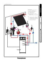
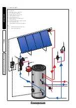
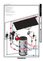
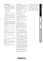
1.11 CONTROL DEVICES UNIT.
The control unit manages the solar system by
controlling the solar unit pump. The various
functions can be programmed via the 3 buttons
(Fig. 1-11) positioned under the display.
1 Forward; 2 Reverse; 3 Set (Selection / opera-
tion mode)
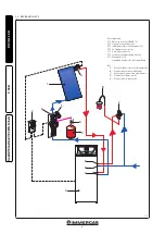
The unit (A) activates the pump when a tem-
perature difference set between the collector
probe (T1) and the boiler probe (T2) (Fig. 1-12).
The installation must only be carried out in
closed and dry environments. To guarantee
regular operation, avoid areas with strong elec-
tromagnetic fields. The regulation control unit
must be detachable from the electric network by
means of an additional device in compliance with
the Laws in force. During installation ensure that
the connection cable to the electric network and
the probe cables remain separated.
The control unit is equipped with 3 relay to which
to connect users such as pumps, valves, etc.
At the time of installation the unit is supplied
pre-set for its correct use. For personalisation
and installation information see the relative
instructions book.
Attention:
the probes supplied are used in ac-
cordance with the pre-fixed purpose:
T1 PT1000 solar probe
T2 NTC boiler probe.
Technical data:
Power Supply
220 ÷ 240 V AC
Stand-by
3,5 W
Inputs
2 temperature probes (pt
1000)
2 NTC 10 k probes
Outputs
3 relay
Room temp.
0 ÷ 40 °C
Protection type
IP 20 / DIN40050
Fuse
T 4 A
key:
A - Control
1 - Terminal T2 probe NTC
2 - Terminal T1 probe
PT1000
3 - Terminal T4 probe
PT1000
4 - Terminal T3 probe NTC
5 - terminal connection to
the mains
6 - Relay Terminals 1 -
circulation pump
7 - relay 2 terminal
8 - relay 3 terminal
key:
A - Control
key:
1 - Forward
2 - Reverse
3 - Set (Selection / operation
mode)
Содержание 3.027832
Страница 1: ...V2 HEATING SOLAR PANELS PACKS IE Instruction booklet and warning 1 041485ENG...
Страница 2: ......


