background image

Selenio

TM

 VMG-14+ Hardware Setup Guide

41

Installation Instructions

Gen2 Release 1.4.0

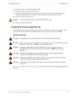
Use


ESD


Protection

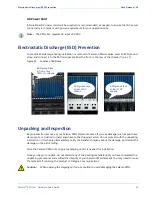
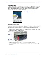
Ground yourself by attaching the plug from the ESD wrist strap to one of the ESD jacks on the chassis 

(

Figure 25

). 

Warning!

Danger of electrostatic discharge. Static electricity can harm delicate components inside the 

Selenio VMG. An ESD wrist strap must be worn before unpacking or exchanging any part or 

electric component. 

Installing


the


Chassis


at


the


Operations


Rack

Note:

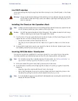
To keep the chassis weight down, do not load the modules until the chassis is secured at the rack. 

Do, not, however, remove the power modules, SCMs, or fan trays. 

Caution:

Do NOT use module handles to lift the VMG system. The handles provided on the fan trays, 

PEMs, or cable trays cannot support the weight of the chassis. 

1.

From the front of the rack, guide the chassis into the rack space until the chassis flanges are flush 

against the rack, and the mounting holes are aligned.

-

One person should hold the chassis from the front. 

-

The other person should work from the chassis rear to guide the chassis onto to the chassis 

shelf.

2.

Using eight (8) chassis rack mount screws, secure the chassis into the rack, tightening each screw 

incrementally until all four are evenly snug-tight. 

Inserting


VMG


Modules—New


System

This section provides basic guidelines for inserting modules for a new system. Steps in this section 

should be used after each module has been removed from its shipping carton and inspected. 

Note:

For instructions about how to handle module with a live system, see 

“Hot Swap Indicators” on 

page 60

 and 

“Handling Application Modules-Live System” on page 61

.

1.

At the card, extend the ejector levers fully by releasing the thumbscrew.

2.

Hold both ejector handles and carefully align the module to the slot as you guide it toward the 

backplane:

-

Align the edge of the module with the slot track in the chassis.

-

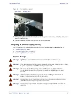
Ensure that the alignment pins on the card are aligned with the corresponding holes on the 

chassis before pushing the card into the backplane connector (

Figure 26

). 

Note:

It is not advisable to apply pressure directly to the faceplate when inserting the card into the slot. 

Always use the ejector handles. 

Содержание Selenio VMG-14+

Страница 1: ...SelenioTM VMG 14 01 Jun 2015 Revision A Hardware Setup Guide ...

Страница 2: ...esign specifications components or documentation as progress may warrant to improve the performance of the product Trademarks SelenioTM and TelurioTM are trademarks of Imagine Communications Microsoft and Windows are registered trademarks of Microsoft Corporation All other trademarks and trade names are the property of their respective companies Patents The products described herein are covered by...

Страница 3: ...mmunications branding 250 0248 01 Rev A N A 12 19 13 Recommended Ethernet cable routing information and doc maintenance Updates to Initialization chapter to incorporate current Element Manager screens 250 0211 01 Rev A N A 6 15 13 Add NPM2 TCM2 TCM2 Add new DC PEM Terminal Block Cover 250 0177 01 Rev A Release 3 1 3 11 15 12 Updated hardware two fan trays Correct numbering for SCMs and AC PSUs 250...

Страница 4: ...tures 13 VMG 14 Chassis and Components 14 Chassis Front 15 Chassis Rear 17 Basic Chassis Populations 18 Shelf Control Managers 19 Fan Trays 21 Fan Filter Tray 22 Network Processor Modules 23 NPM and NPM2 Interfaces 24 NPM and NPM2 LEDs 24 NPM and NPM2 Management and Serial Ports 25 VMG 14 System Modules 26 Video Processor Module 27 Transcoding Modules 28 Application Media Processor 29 System Power...

Страница 5: ...n Preparation 51 Required equipment 51 Steps 51 Chapter 4 Initial Configuration 52 In This Chapter 52 Selenio VMG Physical and Virtual IP Addresses 52 Prerequisites 53 Using TCON Temporary Console to Set Initial Configuration 53 The TCON Main Menu 54 Viewing Current Configuration 54 Setting Network Addresses for the NPM 55 Verifying Gateway Connectivity 55 Viewing VMG Build Information 56 Using El...

Страница 6: ... System Specifications 68 In This Chapter 68 Application Modules 68 Input Output Interfaces 69 Redundancy 69 Compliance 70 Safety 70 Physical Dimensions 71 Weight Specifications 71 Power Specifications 72 DC Power 72 AC Power 72 Environmental Specifications 73 Appendix A Localized Cautions and Warnings 74 In This Appendix 74 Appendix A Conformity and Safety Information 80 Declarations of Conformit...

Страница 7: ...6 Card insertion alignment 42 Figure 27 Chassis rear Ground and Logic Ground DC System 43 Figure 28 DC PEM Cable Connectors 43 Figure 29 Chassis Ground and Logic Ground AC Systems 45 Figure 30 AC Power Supply Unit Ejector Insertion Lever Open 45 Figure 31 AC Power Supply Unit Ejector Insertion Lever Close 46 Figure 32 AC Power Entry Modules with Imagine Communications Supplied Cords 46 Figure 33 N...

Страница 8: ...31 Table 15 DC PEM LEDs 33 Table 16 DC Ground Connection Specifications 38 Table 17 DC Power Connection Specifications 38 Table 18 Hot Swap LED 60 Table 19 Hot Swap LED Reference 62 Table 20 FRU Reference for VMG 14 66 Table 21 Application Modules 68 Table 22 Input Output interfaces 69 Table 23 System and Component Level Redundancy 69 Table 24 Regulatory Standards Compliance 70 Table 25 Safety Spe...

Страница 9: ...s a detailed description of the VMG 14 features and components Chapter 3 Physical Installation describes the initial steps and requirements for installing the VMG 14 Chapter 4 Initial Configuration describes how to prepare a GEN1 system VMG 14 populated with one or more NPM cards for management by the VMG Element Manager Chapter 5 Troubleshooting and Maintenance provides information about LED indi...

Страница 10: ...t également que le fait de ne pas suivre les instructions peut causer des dommages à l équipement ou résulter en une perte de données Das links abgebildete Symbol Vorsicht weist darauf hin dass ein Vorgang unerwünschte Konsequenzen haben kann falls die Anweisungen nicht korrekt befolgt werden Das Symbol Vorsicht weist außerdem darauf hin dass Geräte beschädigt oder Daten verloren gehen können wenn...

Страница 11: ...omer Support for assistance with VMG installation initial configuration or other VMG product issues See also the RBG Networks web site at http www rgbnetworks com support for more details Table 2 Contact Information for Product Returns To Do This Use this contact information Return product Request authorization from Imagine Communications to return materials Customer Portal http support rgbnetwork...

Страница 12: ...nsity digital video solution per rack unit for grooming statistical multiplexing and digital program insertion DPI and transcoding The VMG 14 is fully MPEG 2 and H 264 compliant and interoperable with leading video industry equipment it shares the same software functionality and application modules NPMs AMPs TCMs and VPMs as all other VMG systems This chassis is available either as an AC or DC sys...

Страница 13: ...ures Up to 300 watts per slot Web based embedded management Front loading hot swappable Video Processor Modules VPMs Transcoding Modules TCM TCM2 TCM2 Network Processor Modules NPM or NPM2 Application Media Processors AMPs and two fan trays Redundancy Intelligent Platform Management Bus IPMB interfaces in a radial configuration 1 1 Shelf Control Manager SCM 1 1 NPM or NPM2 and AMP redundancy N M V...

Страница 14: ...atform fitted either for 13 RU DC system or 14 RU AC system The front of the VMG 14 chassis cage accommodates all system and application modules For AC systems Figure 3 the front also includes the AC PSUs located in the power bay at the base of the system Figure 2 VMG 14 DC System Figure 3 VMG 14 AC System FRONT 13 RU REAR 19 21 FRONT REAR 14 RU 20 19 ...

Страница 15: ... Basic Chassis Populations on page 18 for more information System modules fit into numbered slots from left 1 to right 14 Up to two Shelf Manager modules fit into the two vertical slots at the left edge of the chassis alongside slot 1 The AC Figure 4 and DC Figure 5 VMG chassis are identical except for the inclusion of AC PSUs at the base of the AC chassis For slot assignments see Table 3 Rack mou...

Страница 16: ...up Guide 16 VMG 14 Chassis and Components Gen2 Release 1 4 0 Figure 5 VMG 14 Front DC System Air Intake Grid Fan Trays Fan Filter Tray Cable Management Bracket Card Cage Slots 1 through 14 ESD Jack Shelf Control Modules SCM 2 SCM 1 ...

Страница 17: ...ry modules at the base of the system All slots at the rear card cage are covered with RTMs These must not be removed Figure 6 VMG 14 Rear AC System Figure 7 VMG 14 Rear DC System Card Cage Slots 1 through 14 for RTMs ESD Jack Air Intake Grid Power Bay AC PEMs Chassis GND Card Cage Slots 1 through 14 for RTMs ESD Jack Power Bay DC PEMs Chassis GND ...

Страница 18: ...r NPM2 2 Front slots 1 and 2 System modules Family of modules that includes AMP TCM TCM2 TCM2 and VPM Compatibility Notes The TCM AMP and VPM is compatible with NPM The TCM2 or TCM2 is compatible with NPM2 only Various models of TCM cards cannot be mixed Use only TCM TCM2 or TCM2 in your VMG 14 See also VMG 14 System Modules on page 26 AMP 2 Others up to 12 Front slots 3 through 14 Shelf Control M...

Страница 19: ...ler Panels Front Filler RTM Filler Panels See also Filler Panels on page 34 all empty slots Fan Tray See also Fan Trays on page 21 2 Fan Tray slot below cable management tray Fan Filter Tray See also Fan Filter Tray on page 22 1 Front of chassis above fan trays and below cable management tray Table 3 VMG 14 Chassis Modules and Components Continued Name Description System Capacity Slot Assignments ...

Страница 20: ...ing green Note that the RJ45 LEDs illuminate even if the cable is not inserted to report status of Ethernet link activity over the VMG 14 backplane 10 100 link status and activity 10 The RJ 45 port is operating in 10 Mbps mode data is being received or transmitted at 10 Mbps 100 The RJ 45 port is operating in 100 Mbps mode data is being received or transmitted at 100 Mbps Pinouts for this port are...

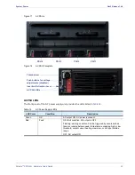
Страница 21: ...SCMs the remaining fans continue to run at full speed The fan trays are hot swappable field replaceable units The VMG 14 chassis contains two fan trays which fit into the base of the chassis at the front Each fan tray contains six fans Figure 9 Figure 9 Fan Trays and Fans Fan Tray LEDs Fan Tray LEDs are located on the Fan Tray front panel Figure 10 and are described in Table 6 Figure 10 Fan Tray L...

Страница 22: ...e grid shown below must be uppermost when installing the Fan Tray Filter at the VMG 14 Figure 11 VMG 14 Fan Filter Fan filter maintenance and replacement information is provided in Fan Tray Servicing on page 64 Table 6 Fan Tray LEDs Color Description Status Condition Red Alarm LED Solid Red Indicates a failure condition Also this LED is lit upon system power up Thereafter the LED is either OFF or ...

Страница 23: ... 7 NPM Models Name Front Panel Label Description System Capacity Slot Assignments Network Processor Module NPM Purpose receive and transmit MPEG 2 and H 264 transport streams carried in an SPTS and or MPTS encapsulated with UDP IP or RTP UDP IP over GigE or 10GigE in GEN1 VMG System management functions Supports 1 1 module redundancy Up to two At least one is required 1 2 Network Processor Module2...

Страница 24: ... optical modules that are IEEE 802 3ae compliant with data rates of 10 3125Gbps The NPM supports XFP modules with wavelengths of 850nm for distances from 26 meters to 300 meters depending on the grade of fiber and 1310nm for distances up to 10 kilometers Each 10GigE port receives input as MPEG 2 SPTS and MPTS with unicast or multicast de jitters up to 100ms of network jittering and routes the vide...

Страница 25: ...le port with an RJ 11 connector is also provided Serial Console Configuration NPM and NPM2 19200 baud No parity 8 data bits 1 stop bit no flow control Serial Port Pinouts NPM and NPM2 Status Red Chassis interface is in fault state Green NPM payload powered and out of reset Config Red FPGA configuration in progress Green FPGA configuration is done Fault Red Fault Green In normal operation Backup Re...

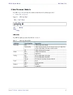
Страница 26: ...PM See also Application Media Processor on page 29 Up to two 3 to pair with NPM slot 1 4 to pair with NPM in slot 2 Video Processor Module VPM Purpose Video and data traffic and control messages for GEN1 VMG Statistical multiplexing for SD programs and HD programs and concurrent transrating Digital ad insertion for CBR or VBR H 264 video and MPEG 2 video program streams See also Video Processor Mo...

Страница 27: ...me Color Condition Description Hot Swap Blue VPM is ready for hot swap Flashing Blue VPM is making transition from hot swap not ready to ready state or from ready state to hot swap not ready state Off VPM is not ready for hot swap Status Red Chassis interface fault Green Payload up Config Red FPGA configuration in progress Green FPGA configuration completed Orange FPGA failure reverting to factory...

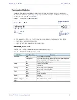
Страница 28: ...2 LEDs The TCM TCM2 TCM2 faceplate provides the LEDs listed in Table 12 Table 12 TCM TCM2 TCM2 Front Panel LEDs LED Name Color Condition Description Hot Swap Blue TCM is ready for hot swap Flashing Blue TCM is making transition from hot swap not ready to ready state or from ready state to hot swap not ready state Off TCM is not ready for hot swap Status Red Chassis interface fault Green Payload up...

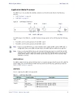
Страница 29: ...e not using AMP Cards you do not need AMP modules and can install TCM and VPM modules in slots 3 and 4 instead If you previously used AMP modules and are now using TCM and or VPM modules in those slots instead you must power cycle the VMG in order for those modules to come up AMP Interfaces The AMP module interfaces with an NPM via direct connectivity between the ETH ports of the AMP to the SFP Gi...

Страница 30: ...ed at the VMG Element Manager if any are removed The AC PEM does not contain status indicators or control features and does not communicate with the SCM However all communications with the AC power system occur between the AC PSUs the SCM The SCM monitors each power supply for presence and operational status Status indicators are provided on the AC PSU Table 14 The VMG 14 AC system uses Imagine Co...

Страница 31: ... Color Condition Description Green OK AC output ON AC power is present Red Fault ON fault condition AC output is OFF Flashing warning condition Can be triggered by events such as fans are running below speed temperature exceeding high or low threshold output current nearing maximum or AC input outside range OFF AC output ON PSU 4 PSU 3 PSU 2 PSU 1 Push buttons for voltage adjustments disabled AC P...

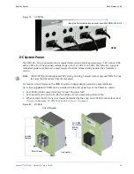
Страница 32: ...at a time to ensure that the system does not lose power For maximum fault tolerance the PEMs should be independently powered by separate feeds Up to four pluggable DC PEMs can be installed into the rear power bay of the VMG 14 chassis Each PEM provides power terminals for one 70A power feed Each power feed consists of a 48V DC cable and its corresponding return cable When cabled the DC connectors ...

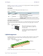
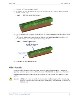
Страница 33: ...e 23 provides a means to organize the input and output cables that connect to various installed modules without impeding the insertion or removal of modules in adjacent slots Figure 22 Cable Management Bracket closed Imagine Communications recommends the following usage with the VMG 14 Cable Tray Table 15 DC PEM LEDs LED Color Condition Description Green Service state Off No power to the PEM Solid...

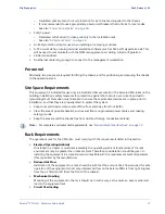
Страница 34: ...the left opening of the tray Figure 24 Managing Ethernet Cable 4 Close the cable management bracket Filler Panels To maintain proper airflow through the chassis all empty slots must be shielded by a filler panel Specific panels are designed for use with front and rear of the VMG 14 as described in this section Imagine Communications provides filler panels for use at the front and rear cage slots o...

Страница 35: ...propriate for your order See also FRU Reference for VMG 14 on page 66 for ordering information Rear Transition Module RTM RTMs are filler panels that cover each of the numbered slots at the rear of the chassis Each is a blank cover that is one slot wide with screws at the left and right The system ships with these installed and Imagine Communications recommends that these always remain in place to...

Страница 36: ...ollowing tools which you should provide at your installation site 3 8 box wrench socket wrench or nut driver to attach cables to the DC PEM 5 16 screwdriver and suitable screws to rack mount the chassis Cable ties and cable clamps to secure power cords and signal cables An anti static pad or treatment if installing on vinyl composite tile linoleum or carpet Site Equipment The installation guidelin...

Страница 37: ...n to ensure these protective devices are in place prior to installation and that they are properly rated to protect the system Keep tools and chassis components off the floor and away from foot traffic Clear the area of possible hazards such as wet floors ungrounded power cables and missing safety grounds Keep the area around the chassis free from dust and foreign conductive material Note For comp...

Страница 38: ...13 RUs for the Selenio VMG DC system Power Connectivity Power cables and cord for use with your Selenio VMG are described in the following sections DC Power Cables next AC Power Cord on page 39 DC Power Cables To ensure the safe and continued operation of the system use specifications for chassis ground cabling Table 16 and power cabling Table 17 At each installed PEM be sure to protect cabled DC ...

Страница 39: ... Selenio VMG shipment arrives If you see damage such as punctures damp spots or crushed corners anywhere on the shipping carton do not proceed with the unpacking instruction in this chapter Immediately notify the transfer company about the damage and record the damage on the bill of lading Store the Selenio VMG in its original packaging until it is needed for installation Once you begin to unpack ...

Страница 40: ...pically pre loaded in the chassis and should not be removed except for servicing Up to two Shelf Control Managers SCMs The SCMs are typically pre loaded in the chassis and should not be removed except for servicing 14 Rear Transition Module RTM Filler Panels The RTMs are always pre loaded in the chassis and should never be removed One serial cable with serial connector One chassis support shelf Pa...

Страница 41: ...the front The other person should work from the chassis rear to guide the chassis onto to the chassis shelf 2 Using eight 8 chassis rack mount screws secure the chassis into the rack tightening each screw incrementally until all four are evenly snug tight Inserting VMG Modules New System This section provides basic guidelines for inserting modules for a new system Steps in this section should be u...

Страница 42: ...ction is essential before connecting supply Warning Before working ensure that the power is removed from the power connection cables When the system is powered on do NOT touch the power terminals Warning Hazardous voltage Before working ensure that the power connection cables are disconnected from power When the system is powered on do NOT touch the power terminals Warning The Selenio VMG is inten...

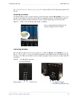
Страница 43: ...centers to connect a double lug Shelf ground terminal cable Figure 27 Chassis rear Ground and Logic Ground DC System Connecting DC Cables Each DC PEM provides two pairs of 1 4 studs 1 4 20 UNC for Return and for 48V DC Figure 28 See DC Power Cables on page 38 for cable specifications appropriate for use with these studs Use the snap on DC PEM terminal block cover provided by Imagine Communications...

Страница 44: ...nings Warning High leakage current Earth connection is essential before connecting supply Warning Before working ensure that the power is removed from the power connection cables When the system is powered on do NOT touch the power terminals Warning Hazardous voltage Before working ensure that the power connection cables are disconnected from power When the system is powered on do NOT touch the po...

Страница 45: ...y seated at the chassis front AC power bay If you are installing the AC power supply unit for your system use the following steps to ensure that each is properly inserted 1 To insert an AC PSU make sure the lever is in open position and ensure that the lever tab can clear the entry cutout of the AC PSU slot Figure 30 Figure 30 AC Power Supply Unit Ejector Insertion Lever Open 2 Guide the power sup...

Страница 46: ...r Imagine Communications power cords Figure 32 Figure 32 AC Power Entry Modules with Imagine Communications Supplied Cords AC Power Cord Use only the AC power cords provided by Imagine Communications Insert one into each applicable AC PEM socket and plug it into the dedicated wall outlet near the installation rack There are no circuit breakers or ON OFF switches AC power is applied to the system d...

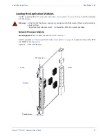
Страница 47: ...ont of the chassis any empty card slot must be fitted with a filler panel to maintain proper air flow The system ships with rear slots 1 14 covered by RTMs Do not remove these Network Processor Modules Slot Assignment Selenio VMG chassis front slot 1 and or 2 Use the guidelines in Inserting VMG Modules New System on page 41 to place and secure the NPM and NPM2 cards Figure 33 Figure 33 NPM or NPM2...

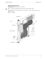
Страница 48: ...signment VMG chassis front slot 3 and or 4 Note The quantity of AMPs installed must equal the quantity of NPMs installed Use the guidelines in Inserting VMG Modules New System on page 41 to place and secure the AMP s Figure 34 Figure 34 AMP Card ETH ports Hot Swap LED Reset Ejector handles Rear Front Thumbscrew Thumbscrew ...

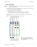
Страница 49: ...M card Connect the AMP card in slot 3 to the NPM in slot 1 Connect the AMP card in slot 4 to the NPM in slot 2 Connect the Ethernet cable to ETH 1 on the AMP and GigE port 8 on the NPM Connect the Ethernet cable to ETH 2 on the AMP and GigE port 7 on the NPM Figure 35 shows the front panel connections for a 2 NPM or NPM2 2 AMP configuration at the Selenio VMG Figure 35 AMP Connections to an NPM or...

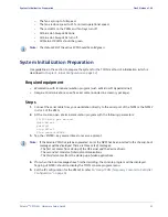
Страница 50: ...thumb screws for all modules are tightly secured Caution Ensure that Imagine Communications supplied filler panels are installed in empty slots This is necessary to maintain proper airflow and prevent air from escaping out of the front of an open slot Power Up and Verify 1 On a DC System connect power to the PEMs On an AC System set the circuit breaker of each AC PEM to be used to the ON position ...

Страница 51: ...1 Connect the serial cable from your workstation directly to the serial port of the NPM or the NPM2 in slot 1 of the VMG 2 At the console open a terminal emulation program with the following parameters 19 200 bits per second data bits 8 parity 0 stop bits 1 flow control NONE 3 Tap the ENTER key several times to receive a prompt Note If the Selenio VMG has just been powered on or the NPM has been i...

Страница 52: ...lement Manager to Finalize Initial Configuration on page 56 Selenio VMG Physical and Virtual IP Addresses To provide NPM redundancy there are two types of IP addresses employed by the Selenio VMG physical and virtual Each NPM installed in the Selenio VMG must have a physical address assigned to it during the initial system configuration See Using TCON Temporary Console to Set Initial Configuration...

Страница 53: ...that the VMG 14 will use for GUI management access Note that 10 0 1x and 10 0 2x subnets are reserved for VMG internal use only and cannot be used for the management interface The address of one or more NTP servers The time zone The address of the syslog server optional Note Although the syslog server is optional it is highly recommended Note The DNS NTP and syslog servers are not required to be o...

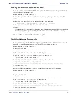
Страница 54: ...nce the management interface is configured for each NPM the NPMs can be rebooted using option 4 of the TCON main menu You can then use a Web browser to access the Element Manager and finish the initial configuration as described in Using Element Manager to Finalize Initial Configuration on page 56 Viewing Current Configuration To view the configuration currently saved to the NPM select 1 from the ...

Страница 55: ... like the following 10 32 144 240 255 255 255 0 10 32 144 1 10 32 11 11 Enter values for each installed NPM in the VMG 14 system Verifying Gateway Connectivity To verify connectivity with the default router gateway select 3 from the TCON main menu Output similar to the following example will be displayed where connectivity is enabled Enter number of your choice 3 Pinging 10 32 144 1 PING 10 32 144...

Страница 56: ...o NPMs are installed the active NPM will be the module in Slot 1 The URL will be the IP address preceded by http e g if the IP address is 10 32 97 181 the URL is http 10 32 97 181 Successful web connection with the VMG results in display of the Video Multiprocessing Gateway Home page Figure 37 Figure 37 Selenio VMG Home Page Note The VMG Element Manager requires that the PC on which it is running ...

Страница 57: ... in the Password field If using an AAA server account type the AAA login name in the User field and the AAA password in the Password field 3 Click Log in or use Alt l to continue with the login Upon logging in the initial view defaults to the Chassis tab as seen in Figure 39 which displays a representation of the physical VMG 14 and its populated slots The System Information window on the right si...

Страница 58: ...n Gen2 Release 1 4 0 Figure 39 Element Manager Chassis View 4 From the main menu bar select Configuration Global from the drop down menu to present the Global Configuration window which defaults to display of the System tab Figure 40 Figure 40 Accessing System Parameters alarm status here syslog ...

Страница 59: ...Figure 41 to access configuration fields for the virtual management IP address of the system The IP address configured here will be used to access the VMG 14 Figure 41 Global Configuration Management Interface Tab 8 In the Virtual IP Address section enter the IP Address Subnet Mask netmask and Gateway default router address if used 9 Click Apply or use Alt a button to commit the values and complet...

Страница 60: ...wrist strap exchanging any part or electrical component Connect your ESD strap to the ESD jack at the rear of the VMG 14 chassis Hot Swap Indicators Before removing or servicing modules on a live system it is important to notice current swap readiness of the module as indicated by the Hot Swap LED at the front panel of the module During operations the Hot Swap LED remains Off until the ejector lev...

Страница 61: ...ening the ejector handles LED indications on the card faceplate when replacing the card which informs if the card is operating properly Figure 42 Module generic ejector handles Removing VMG Modules from a Live System Be sure to have the replacement card or the filler card available whenever removing a card from a live system You should re populate the slot as soon as possible after removing a card...

Страница 62: ...iver size PH1 loosen the four captive screws around the DC PEM faceplate 5 Pull the DC PEM out and away from the DC power bay When the PEM is completely extracted you will see the DC PEM connector at the chassis 6 Guide the new PEM into the empty PEM slot making sure to fully seat the PEM into the connector 7 Using a Phillips screwdriver size PH1 tighten the four captive screws around the DC PEM f...

Страница 63: ...atch into open position and gently guide the AC PSU out and away from the slot 2 Insert the replacement PSU Guide the AC PSU into the empty slot and adjust the latch so that the latch tab can clear the slot cutout then push the AC PSU in until it stops Guide the latch into upright position It should be completely flush with the surface of the front panel when fully closed 3 Insert the thumbscrew a...

Страница 64: ...ds of the module faceplate 5 Check the LEDs to ensure that the module is functioning as expected Warning Some shelf managers can contain a lithium battery There is a risk of explosion if the battery is replaced with an incorrect type Dispose of used batteries according to the instructions Fan Tray Servicing You can remove either of the two fan trays without disruption to service or degradation to ...

Страница 65: ...ss dust collection A dirty air filter can cause overheating of the system Imagine Communications recommends that air filters be replaced every three to six months or more often as dependent on conditions in the operations site To view the location of the Fan Filter Tray see Fan Filter Tray on page 22 Fan Filter Removal Remove the air filter by grasping both handles on the air filter tray and slidi...

Страница 66: ...gather the following information Chassis model and serial number A clear description of the problem Steps to reproduce the problem if applicable Table 20 FRU Reference for VMG 14 Components Spares Part VMG 14 CHASSIS AC VMG 14 AC Chassis VMG 14 CHASSIS DC VMG 14 DC Chassis VMG NPM Network Processing Module VMG NPM2 Network Processing Module 2nd Generation VMG VPM Video Processing Module VMG TCM Tr...

Страница 67: ...m the Customer Portal home page click on the Knowledge Base tab Figure 47 Customer Portal home page Direct and Reseller 3 From the Knowledge Base home page enter the desired search term in the Search box and tap the Enter key Figure 48 Knowledge Base search Direct and Reseller Event Log Analysis If asked to do so by customer support access the system event log You will be instructed on this proced...

Страница 68: ... 71 Power Specifications on page 72 Environmental Specifications on page 73 Application Modules Table 21 Application Modules Module name Function Network Processing Module NPM NPM2 Runs host software and includes GigE input output interfaces Transcoding Module TCM TCM2 TCM2 Provides H 264 MPEG 2 transcoding of streams Video Processing Modules VPM Performs grooming stat muxing DPI program substitut...

Страница 69: ...gE interfaces copper or optical NPM AMP 4 x 10GigE 8x GigE interfaces copper or optical NPM2 Fast Ethernet 1 x 10 100Base T control and management interface NPM 4x10 100Base T control and management interface NPM2 Serial 1 x RJ 45 serial port NPM NPM2 SCM AMP 1x RJ 11 serial port NPM SDI SDI out for testing TCM TCM2 TCM2 Table 23 System and Component Level Redundancy Redundancy Module Redundancy A...

Страница 70: ...Criteria A Radiated RF Field Immunity EN6100 4 3 80 1000 MHz 3 V m Criteria A Modulation 1 kHz 80 AM 1 step size Immunity to Electrical Fast Transients EN61000 4 4 Signal Ports Level 2 0 5 kV Criteria A Power Line Level 2 1 kV Criteria A Surge Immunity EN61000 4 5 1 0 kV 1 2 50 8 20uS Criteria B Un balanced Indoor Cables and shielded cables Common Mode Not applicable to Intra system cables Not app...

Страница 71: ...ot including cable management tray Table 27 Weight Specifications Parameter Value AC chassis cage weight empty 37 9 Kg 83 6 lbs DC chassis cage weight empty 36 0 Kg 79 3 lbs SCM Board weight 0 3 Kg 0 5 lbs DC PEM weight 1 8 Kg 4 0 lbs AC power supply unit weight 2 2 Kg 4 9 lbs Fan tray weight 1 6 Kg 3 5 lbs NPM Board weight 1 5 Kg 3 4 lbs NPM2 Board weight 2 11 Kg 4 65 lbs VPM Board weight 1 3 Kg ...

Страница 72: ...nput Specifications Parameter Value Input Voltage Range 85 to 264 VAC 180 264 V for full 300 watt slot Input Current Max per AC Feed 10A 240 VAC Inrush Current per AC Feed 50A peak AC Power Consumption at Low Line AC Power Consumption at High Line 5400W maximum fully loaded Table 30 AC Power Supply Module Specifications Parameter Value Input Voltage Range 85 264 VAC 47 63Hz Input Current Maximum 1...

Страница 73: ...arameter Value Storage temperature 40º to 70º C 40º to 158º F Operating temperature 0º to 45º C 32º to 113º F Ambient temperature transient operation 5 º to 55 ºC 41º to 131ºF Humidity 5 to 90 non condensing Humidity transient operation 5 to 95 non condensing Altitude 71 to 3028 m 200 to 14 000 ft Operational shock 15 g 8 ms Non operational shock 40 g 11 ms ...

Страница 74: ...bles and Terminals Advisory on page 75 Filler Panels on page 75 Power Safety Hazardous Voltage Advisory on page 76 Grounding Equipment Protective Earth on page 76 Handling Computer Equipment Static Electricity 2 on page 76 Electric Overload Advisory on page 77 Remove Jewelry on page 77 Unpacking on page 77 Lifting on page 78 Polarities on page 78 Filler Panel Advisory on page 78 Handling Computer ...

Страница 75: ...on Lorsque le système est allumé ne touchez PAS les bornes électriques Warnung Stellen Sie vor Beginn der Arbeiten sicher dass die Netzkabel stromlos sind Wenn das System eingeschaltet ist dürfen die Stromanschlüsse NICHT berührt werden Page number and subject Statement type Statement Page 50 Rack Requirements Filler Panels Caution Ensure that Imagine Communications supplied filler panels are inst...

Страница 76: ... Selenio VMG is intended to be grounded Ensure that the ground terminals are connected to the Protective Earth PE of the building Avertissement Le VMG doit être mis à la terre Assurez vous que les bornes de terre sont connectées à la terre du bâtiment Warnung Das VMG muss geerdet werden Vergewissern Sie sich dass die Erdungsanschlüsse mit dem Schutzleiter des Gebäudes verbunden sind Page number an...

Страница 77: ...s für das VMG zulässigen Bereichs an die Anschlüsse angelegt werden Page number and subject Statement type Statement Page 42 DC Power Supply Electrical Warnings Warning Remove jewelry rings watches etc before working on equipment that is connected to power lines Avertissement Retirez vos bijoux bagues montres etc avant de travailler sur un équipement branché sur l électricité Warnung Legen Sie vor...

Страница 78: ...tement type Statement Page 44 DC Cables Polarity Caution Verify the correct polarity of the 48V DC and the RTN cables Attention Vérifiez la polarité du circuit 48 Vcc et des câbles RTN Vorsicht Vergewissern Sie sich dass das 48 V Gleichstromkabel und das RTN Kabel richtig gepolt sind Page number and subject Statement type Statement Page 47 Filler panel requirements Warning At the front of the chas...

Страница 79: ... des Gehäuses können durch statische Elektrizität beschädigt werden Beim Austauschen von Tei len oder elektrischen Komponenten muss stets ein Erdungsarmband getragen werden Page number and subject Statement type Statement Page 64 Lithium Battery Warning Some shelf managers can contain a lithium battery There is a risk of explosion if the battery is replaced with an incorrect type Dispose of used b...

Страница 80: ...technology equipment Radio disturbance characteristics Limits and methods of measurement Class A CISPR 22 2008 Information technology equipment Radio disturbance characteristics Limits and methods of measurement Class A AS NZS CISPR 22 2009 Information technology equipment Radio disturbance characteristics Limits and methods of measurement Class A EN 55024 2010 Information technology equipment Imm...

Страница 81: ...with FCC requirements for Subpart B of Part 15 of FCC Rules for Class A or Class B digital devices In that event your right to use the equipment may be limited by FCC regulations and you may be required to correct any interference to radio or television communications at your own expense For Class A Equipment Note This equipment has been tested and found to comply with the limits for a Class A dig...

Страница 82: ...mmunity test IEC 6100 4 2 2008 EN 6100 4 2 2009 IEC 6100 4 3 2006 A1 2007 A2 2010 EN 61000 4 3 2006 A1 2008 A2 2010 Section 3 Radiated radio frequency electromagnetic field immunity test IEC 61000 4 2 2006 A1 2007 A2 2010 EN 61000 4 3 2006 A1 2008 A2 2010 IEC 6100 4 4 2004 EN 61000 4 4 2004 Section 4 Electrical fast transient burst immunity test IEC 61000 4 4 2012 EN 61000 4 4 2012 IEC 61000 4 5 2...

Страница 83: ...on for radio disturbance and immunity measuring apparatus and methods Part 1 1 Radio disturbance and immunity measuring apparatus Measuring apparatus CISPR 16 1 2006 A1 2006 A2 2007 CISPR 16 1 2 2003 A1 2004 A2 2006 Specification for radio disturbance and immunity measuring apparatus and methods Part 1 2 Radio disturbance and immunity measuring apparatus Ancillary equipment Conducted disturbance C...

Страница 84: ...y measuring apparatus and method Part 1 1 Radio disturbance and immunity measuring apparatus Measuring apparatus CISPR 16 1 2 Ed1 2 2006 Specification for radio disturbance and immunity measuring apparatus and methods Part 1 2 Radio disturbance and immunity measuring apparatus Measuring apparatus Ancillary equipment Conducted disturbances CISPR 16 1 4 Ed2 0 2007 Specification for radio disturbance...

Страница 85: ...tation strategies B Bandwidth The maximum amount of data that a transmission device is capable of carrying C CBR Constant Bit Rate Constant bit rate encoding ensures that the rate at which a codec s output is consumed is constant Because it is the maximum bitrate that matters CBR is useful for streaming multimedia content on limited capacity channels See also VBR Codec A program or device used for...

Страница 86: ...econd GUI Graphical User Interface A type of user interface that allows people to interact with electronic devices H H 264 A block oriented motion compensation based codec It is equivalent to the MPEG 4 Part 10 standard HD High Definition High resolution digital television combined with Dolby Digital surround sound AC 3 Headend A regional distribution point in a television system I IEEE Institute ...

Страница 87: ...ing files L LED Light Emitting Diode A semiconductor diode that emits light when current passes through it LEDs are used as indicators M MPEG Moving Pictures Experts Group A joint standards working group of ISO IEC that develops video and audio encoding standards MPEG 2 A transport audio and video standard for compression and storage of broadcast quality television MPEG 4 A graphics and video comp...

Страница 88: ...ications RTM Rear Transition Module RU Rack Unit A common increment of equipment space height The height of 1 RU is 1 75 inches S SCTE Society of Cable Telecommunications Engineers An organization that develops training for cable television installers and engineers and standards for the cable industry SD Standard Definition Television systems that have a resolution that meets standards but not con...

Страница 89: ... Datagram Protocol A connectionless transport protocol in the TCP IP Internet protocol suite that runs over the IP network protocol UDP provides a direct way to send information over an IP network It is used primarily for broadcasting messages over a network V VBR Variable Bit Rate VBR streams vary in bandwidth over time VIA Video Intelligence Architecture An FPGA based modular architecture develo...

Страница 90: ... Small Form Factor Pluggable 10 Gigabit Small Form Factor Pluggable SFP The XFP is a pluggable hot swappable optical interface for 10 Gigabit SONET SDH Fibre Channel Gigabit Ethernet and other applications XFP modules are optical transceivers typically 1310nm or 1550nm Optical XFPs include digital diagnostics ...

Страница 91: ...nition HD 12 I IEEE 802 3ab 25 initial configuration network addresses 59 using Element Manager 56 using TCON 54 Intelligent Platform Management Bus IPMB 13 interfaces 69 IPTV 12 J Java 56 JRE 56 L LEDs AC PEM 63 AC power supply 31 AMP 29 DC PEM 31 33 fan trays 22 NPM 24 TCM TCM2 TCM2 28 VPM 27 M mechanical loading 37 module insertion new system 41 removal live system 61 replacement live system 62...

Страница 92: ...nnector 25 S SCM 18 SCTE 30 24 server DNS 53 NTP 53 59 Shelf Control Manager SCM replacement 64 Single Program Transport Streams SPTS 24 site preparation 36 site requirements personnel 37 rack 37 space 37 standard definition SD 12 statistical multiplexing 26 support shelf 40 system modules 18 T TCM 13 TCM TCM2 TCM2 26 TCON 51 53 terminal configuration 53 Transcoding Module TCM TCM2 TCM2 13 28 U un...

Отзывы: