Illusion Esprit EGL63LP Скачать руководство пользователя страница 14

FREESTANDING MANUAL 2014

Va l u e   &   Q u a l i t y   I n   G a s   L o g   F i r e s

1

7

6

4

2

5

3

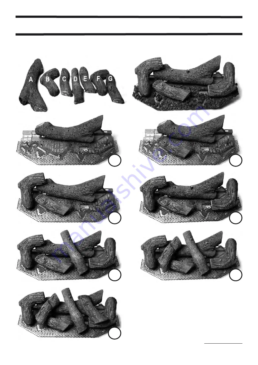
FITTING THE LOG SET  - MODELS EGL70NG, EGL70LP, EGL69NG, EGL69LP

12

LOGS ARE NUMBERED ON THE        

UNDERSIDE

A

E

F

B

D

G

C

INSTALLATION SEQUENCE = A-E-F-B-D-G-C

ADD COALS AS THE 

LOGS ARE FITTED

Содержание Esprit EGL63LP

Страница 1: ...k resistant Contains no asbestos THESE APPLIANCES HAVE BEEN TESTED IN ACCORDANCE WITH AG 103 FOR INSTALLATION AND OPERATION AS DESCRIBED IN THIS MANUAL AND HAVE BEEN CERTIFIED BY THE AUSTRALIAN GAS AS...

Страница 2: ...ELS UGL63 UGL70 ARE DESIGNED AND TESTED TO BE INSTALLED WITH THE SUPPLIED FLUE KIT ONLY THESE UNITS MUST ONLY BE INSTALLED BY AN AUTHORISED INSTALLER Va l u e Q u a l i t y I n G a s L o g F i r e s T...

Страница 3: ...FREESTANDING MANUAL JAN 2014 Va l u e Q u a l i t y I n G a s L o g F i r e s EGL63NG EGL63LP DIMENSIONS 1 GAS INLET RHS REAR 478mm 451mm 549mm 749mm 670mm 670mm 478mm 36mm 50mm...

Страница 4: ...FREESTANDING MANUAL 2014 EGL70NG EGL70LP DIMENSIONS 2 Va l u e Q u a l i t y I n G a s L o g F i r e s GAS INLET RHS REAR 36mm 50mm 478mm 451mm 549mm 799mm 770mm 770mm 478mm...

Страница 5: ...ure kPa 83 73 1 25 2 25 Gas Consumption Mj h 33 40 28 37 Gas Type NAT NAT LP LP Average Efficiency 76 1 77 9 72 72 Max Output kW h 7 19 8 6 5 74 7 58 Manufactured by Illusion Australia Pty Ltd 145 Sth...

Страница 6: ...OURS HOME IF YOU CAN SMELL GAS DO NOT USE MOBILE PHONES OR ANY ELECTRICAL APPLIANCE OR ELECTRIC SWITCH IN THE BUILDING PILOT FLAME IGNITION Depress and turn the control knob to the PILOT position Depr...

Страница 7: ...nce must be installed with an approved flue system which terminates outside the building A flue system must never terminate within the roof cavity 5 The unit should be checked periodically for lint Th...

Страница 8: ...art number LS1 and Model EGL70 requires Log kit part number LS2 Check to see that the correct log kit is supplied Open the FLUE KIT carton and check to see all components are supplied including the fl...

Страница 9: ...EGL70NG and EGL70LP must only be installed with the minimum distances shown below Note that these appliances have a DRAFT DIVERTER at the rear of the unit which exits at the rear and must not be alter...

Страница 10: ...014 8 Va l u e Q u a l i t y I n G a s L o g F i r e s INSTALLATION EXAMPLES PLEASE NOTE ALL ILLUSION GAS HEATERS MUST BE INSTALLED BY A QUALIFIED GASFITTER IN ACCORDANCE WITH AUSTRALIAN STANDARDS AS...

Страница 11: ...Place log number 4 over middle pin in rear log and right pin in the burner plate Note the positions of the bumps in log No 4 The narrow end of log number 4 is towards the rear of the heater 5 Place lo...

Страница 12: ...e Q u a l i t y I n G a s L o g F i r e s FITTING THE LOG SET MODELS EGL63NG EGL63LP EGL62NG EGL62LP 10 ADD COALS AS THE LOGS ARE FITTED INSTALLATION SEQUENCE 1 2 3 4 5 6 2 2 3 3 4 4 1 1 6 6 LOGS ARE...

Страница 13: ...pproximately level with the top of log A 5 Insert a ceramic pin and the metal spacer into the second from right hole in log A The pointed end of the spacer should face up Insert log D over the pin spa...

Страница 14: ...Q u a l i t y I n G a s L o g F i r e s 1 7 6 4 2 5 3 FITTING THE LOG SET MODELS EGL70NG EGL70LP EGL69NG EGL69LP 12 LOGS ARE NUMBERED ON THE UNDERSIDE A E F B D G C INSTALLATION SEQUENCE A E F B D G C...

Страница 15: ...SHOULD BE CHECKED AT THE PRESSURE TEST POINT SEE BELOW NOTE BOTH INLET AND MANIFOLD PRESSURES SHOULD BE CHECKED USING THE VALVE PRESSURE PORTS ON THE GAS VALVE PROCEDURE TURN VALVE TO OFF POSITION LO...

Страница 16: ...AND OTHER GAS APPLIANCES IN THE HOME SHOULD BE RUNNING WHEN THE HEATER IS TESTED FOR FLUE SPILLAGE TO TEST FOR SPILLAGE THE HEATER SHOULD BE LIT AND SET TO HIGH WAIT 10 MINUTES THEN TEST FOR DRAFT AT...

Страница 17: ...ames periodically The flames should be steady and not lifting off the burner holes If there is a problem call an authorized person or your local dealer 4 The appliance and flue system must be inspecte...

Страница 18: ...PANEL OF HEATER AS SHOWN ABOVE SWING BOTH LEFT AND RIGHT HAND SIDE PANELS OPEN WHILST PRESSING THE DOOR FORWARD PULL FOUR TOGGLE CLAMP LEVERS TOWARDS THE FRONT OF HEATER AND UNCLIP AS SHOWN REMOVE THE...

Страница 19: ...Spare parts are available from your supplier Refer to rear of this manual for contact details 2 5 1 3 4 6 7 9 11 12 13 8 10 1 DOOR ASSEMBLY 2 TOP PANEL 3 TOP MOUNTING PANEL 4 FIREBOX 5 FAN AIR DUCT 6...

Страница 20: ...lso shut down the fan 10 to 15 minutes after the heater is turned off once the firebox has cooled sufficiently REMOTE CONTROLLER OPTION The above features apply even if the unit is fitted with a new O...

Страница 21: ...house and does not require line of sight It is a fully featured programmable unit which can be wall mounted in the supplied cradle No need for a seperate wall thermostat The remote can be programmed f...

Страница 22: ...ON THE LOGS AND OR DOOR GLASS 2 YOU CAN SMELL GAS 3 THE FLAME PATTERN IS INCONSISTENT AND APPEARS TO BE LIFTING OFF THE BURNER 4 YOU CAN SMELL THE PRODUCTS OF THE FLUE WITHIN THE ROOM IN WHICH THE AP...

Страница 23: ...active SOLUTION The gas valve sensor Thermopile may be faulty Contact your Dealer SYMPTOM The logs have a build up of black soot in some areas POSSIBLE CAUSE Usually indicates incorrect positioning of...

Страница 24: ...s L o g F i r e s Illusion Gas Log Fires State Dealer Contact List Head Office 145 Sth Gippsland Hwy Dandenong Victoria Australia 3175 Phone 61 3 9793 7520 www Illusionfires com au service Illusionfir...

Страница 25: ...phone 03 9793 7520 Email service Illusionfires com au WEB www Illusionfires com au Illusion Australia Pty Ltd reserves the right to alter specifications contained in this publication without notice Il...

Отзывы: