background image

12

 NOTE

Observe the operating instructions 

for the devices.

Check if the voltage specified on the type plate matches the avail-
able mains voltage. If these conditions are met, the device is ready 
for operation when it is plugged in to the mains.

The socket used must be earthed 
(grounded contact). 

Otherwise safe operation is not guaranteed or the device may be 
damaged.
Observe the ambient conditions indicated under “Technical data”.

Commissioning

Switching on

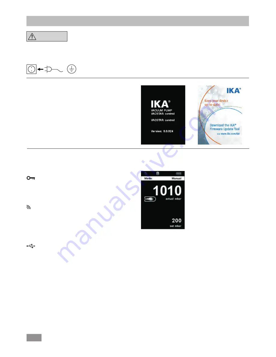
After switching off via the main switch (Fig. 1, (4)), the device type, 

device designation, user-defined device name and the firmware 

version are shown in the display.

Firmware Update Tool

After the start screen, the information start screen for the Firmwa-
re Update Tool appears. You can use the tool to update the soft-
ware of your IKA device to the latest version. Firmware updates 
contain new functions or optimisations of previous functions. You 
can download the Firmware Update Tool at www.ika.de/fut.

Working screen (factory settings)

The following working screen appears automatically in the display.

Explanation of symbols on the working screen

  Lock key:

This symbol means that the function of the key and of the rotary 
knob for controlling the vacuum controller are disabled. The sym-
bol no longer appears if the functions are enabled once again by 
pressing the lock key a second time (min. 1 sec.).

  Bluetooth

®

:

This symbol means the  station and the WiCo are communicating 
via Bluetooth

®

. The symbol no longer appears if no Bluetooth

® 

communication is being performed.

B

  Operating mode:

The operating mode currently selected (A, B, C, D).

  USB:

The vacuum controller is communicating via a USB cable. The sym-
bol no longer appears if no USB cable is being used for communi-
cating with the station.

Timer:
Appears when the timer display is active in the display.

PC:
The vacuum controller is connected to a computer and the device 
is being controlled from the computer.

Содержание Vacstar control

Страница 1: ...20000023248 IKA Vacstar control IKA Vacstar control_102018 Operating instructions EN ...

Страница 2: ...an Ventilation slit 7 Hose connection for suction line d 8 mm INLET 8 USB interface 9 RS 232 interface 10 Water Valve Connection 11 Hose connection for pressure line d 8 mm OUTLET 12 Mains cable connection 13 Pressure Device 14 Hose connection for ventilation line d 8mm 15 Hose connection for load line d 8mm 16 Hose connection for suction line d 8 mm INLET 17 Clamp 18 Receiving flask 1 2 3 4 14 12...

Страница 3: ...9 1 EN 301489 17 EU Declaration of conformity Explanation of warning symbols According to IKA s Terms and Conditions of sale and delivery this product is covered by a warranty for a period of 24 months Please contact your dealer for any warranty claims If you wish you can send the device directly to our factory Please provide the sales invoice and state the reasons for your guarantee claim In this...

Страница 4: ...ore commissioning check that all the housing parts are present and fastened to the device Do not lift the pump if the handle is loose and the handle securing screw Fig 2 5 is loose or missing Only switch ON the pump if the pump is standing vertically Connect the hose connections INLET OUTLET and interfaces in accordance with the labelling on the device and the operating instructions Ensure that th...

Страница 5: ...thium polymer battery pack must only be used and charged in IKA products designed for use with this battery pack When the battery pack is inserted it should slide in easily and without resistance Do not force it If the battery pack is removed for an extended period of time store it in a sealed plastic bag to prevent short circuiting due to moisture or contact with metal components The operating te...

Страница 6: ...Vacstar control Power cord set USB A USB B cable A USB A USB micro B Vacuum hose 1 m Vacuum Hose 0 3 m connection Vacstar to Vacuum Safety VSE 1 Vacuum Safety VSE 1 Wireless Controller WiCo OS 1 0 power supply unit for WiCo Adapter UK Adapter USA China Adapter Australia Adapter Europe Switzerland Cover Screw driver screw driver to screw WiCo on station Bracket Flask Spherical clamp User guide Warr...

Страница 7: ...h no load at the end of the process no load operation approx 3 up to max 5 minutes to dispel any residues in the pump If applicable vent the recipient To do this remove the suction line during manual operation NOTE Observe the operating instructions of the relevant devices Area of use indoor use only Laboratories Schools Pharmacies Universities The device is suitable for use in all areas EMC class...

Страница 8: ...the station the rechargeable battery is automatically recharged via the contacts page 11 A Q The rechargeable battery can also be charged via the USB port of the WiCo In automatic operation with controlled speed the pump reduces its speed when it reaches the target value If the leakage rate in the entire system is low enough the speed may even be set to zero Schematic view of speed vacuum control ...

Страница 9: ...elling on the pump and the operating instruc tions The connections are barbed hose connectors Ensure that the hos es have hose clips if applicable Lay the hoses in such a way that no condensate can flow into the pump Ensure that the air can enter the ventilation slit Fig 2 6 unhin dered Install a condensate separator e g a VSW 1 in the suction line before the intake spigot of the pump to protect a...

Страница 10: ...bsorber to the end NOTE Put the end of the hose in the fume hood Check there is a free outlet on the pressurised side Do not use a throttle on the pres surised side and do not close the outlet Connect the exhaust line to this connection Fig 2 8 USB interface Connect the vacuum pump IKA Vacstar control to a PC with a USB A USB B cable Any device software updates can be loaded using the IKA FUT soft...

Страница 11: ... the settings in the menu L Securing screw Secure the Wico to the station M On Off key Switching the Wireless Controller on and off N Lock key Key disable and rotary push knob disable O Vent key To vent the load if necessary during the vacuum process P Pause key Temporarily stop the function of the device for required period Note can resume the function by pressing the button again Q PCB Contact W...

Страница 12: ...ions or optimisations of previous functions You can download the Firmware Update Tool at www ika de fut Working screen factory settings The following working screen appears automatically in the display Explanation of symbols on the working screen Lock key This symbol means that the function of the key and of the rotary knob for controlling the vacuum controller are disabled The sym bol no longer a...

Страница 13: ...urn to the previous menu or working screen Note The menu option activated is highlighted blue in the display Menus which are grayed out are inactive Navigation menu Press the Menu key H and turn the rotary push knob K Press the Back key I or the Menu key H Note If you press the Menu key H the system skips directly back to the working screen If you press the Back key I the system skips back to the ...

Страница 14: ... update info Communication Brightness Pressure max Operating mode Logic version Volume Pressure min Pump max Pump min Key tone Device name Firmware Update Info Display version Activated Deactivated 20 05 00 mm ss Add solvente No 1 5 Pump Display Black White Background Standard Mode Battery Mode Sound Factory setting Menu values Programs All Bluetooth Remote control Paring Information Deactivated D...

Страница 15: ...g the knob again stops the process Cleaning NOTE The Cleaning menu item increases the service life of the pump since solvent residues do not remain in side the pump The cleaning of the pump ensures that solvent residues are re moved in the pump after the measurement For this purpose the pump should run at a low speed rate while the system is venting The air flowing through the pump ensures that th...

Страница 16: ...tion for a standard time The device can emit a signal beep after the set target time has elapsed Operating mode 1 Press the Menu key N 2 Select the menu Operating mode and confirm the input 3 Select the following settings Operating mode A In this operating mode the set target value is not saved when the current run comes to an end or the device is switched off Limits In this menu limits for the ta...

Страница 17: ... segment in the program Delete Deletes the selected program If a selected program is deleted by pressing on menu option Delete with rotary push knob all the program parameters will be emptied The tick disappears Details for editing the program In this program you can define up to 10 segments The selected segment is highlighted Then you can edit delete or insert a seg ment in this program The progr...

Страница 18: ...t In the Time Out menu you can set a time limit This time limit applies if there is a communication failure between the IKA Vacstar and the WiCo or the communication range is exceeded The IKA Vacstar will continue to run at the set speed until the set time has expired After that the IKA Vacstar will continue to run at the set safety pressure manual mode or safety pump rate Pump mode see the Safety...

Страница 19: ... to choose menu values pro grams and all Select the option which is going to be reset Communication The Device name option allows you to input a device name The device name appears on the opening screen when the device is switched on This can be useful when using multiple devices with different set tings This also facilitates the identification of each device when communicating with a PC via USB R...

Страница 20: ... space code hex 0x20 Each individual command including parameters and data and all responses are completed with CRLF code hex 0x20 hex 0x0d hex 0x0A and can have a maximum length of 50 characters The dot is used for decimal separators in a floating point val ue code hex 0x2E The details given above generally comply with the recommen dations of NAMUR NAMUR recommendations for the design of electric...

Страница 21: ...h you can obtain from IKA or can download a version for printing from the IKA website www ika de If your appliance requires repair return it in its original packaging Storage packaging is not sufficient also use appropriate transport packaging 1 2 RxD 3TxD 4 5 GND 6 7 RTS 8 CTS 9 1 RxD 2 TxD 3 4 GND 5 6 RTS 7 CTS 8 9 PC 1 2 3 4 5 6 7 8 9 9 8 7 6 5 4 3 2 1 Watchdog functions monitoring of the seria...

Страница 22: ...l service department Error 8 Speed sensor fault Device can t detect the pump speed The sensor occurs some unknown errors that device can t read the speed value Call service department Error 9 Storage Error Read or write internal flash error Read or write internal flash error Call service department In the event that the fault cannot be eliminated using the measures described or another error code ...

Страница 23: ...um sensor type ceramic Al2O3 Pressure max for pressure sensor bar 1 2 Measurement range absolute min mbar 1 Measurement range absolute max mbar 1030 Resolution pressure mbar 1 Measurement uncertainty mbar 1 Venting valve yes Condensate trap yes Emission condenser yes Timer yes Noise at low pressure dB A 54 Material in contact with medium Al2O3 PTFE FPM PPS Housing material Alu cast coating Mode au...

Страница 24: ...ax C 40 Permissible relative humidity 80 Protection class according to DIN EN 60529 IP 20 USB interface yes RS 232 interface yes Voltage V 100 240 Frequency Hz 50 60 Power input W 140 Power input standby W 1 5 Average values Subject to technical changes ...

Страница 25: ...25 ...

Страница 26: ...IKA Werke GmbH Co KG Janke Kunkel Str 10 D 79219 Staufen Tel 49 7633 831 0 Fax 49 7633 831 98 sales ika de www ika com ...

Отзывы: