10
8.1.2 The switched state
If the target is in the enable zone and if there is no sensor error, both outputs A1
and A2 (OSSDs) are enabled (logic "1").
8.1.3 Output characteristics
The interface of the devices complies with interface type C class 1 according to
the ZVEI position paper CB24I Ed. 2.0.x.
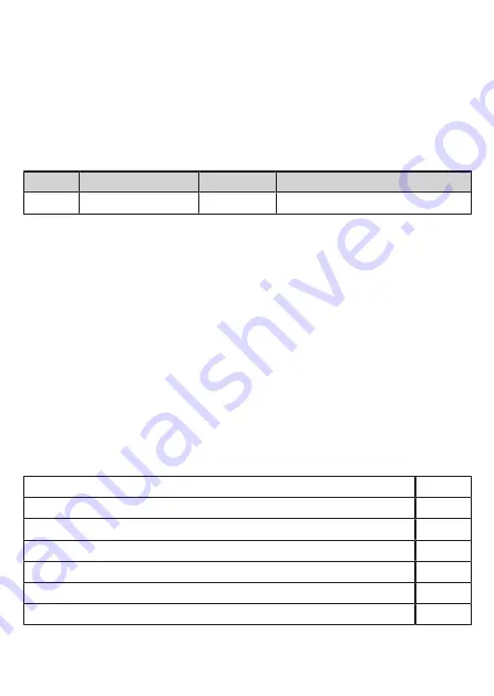
Interface type
Suitable interface type
Source
C1
Receiver
C1
Tab. 1: Identification key
8.1.4 Cross fault / short circuit
• A cross fault between both outputs (A1 and A2) is detected by the fail-safe
sensor and results in the outputs (OSSD) being switched off after 4 s at the
latest. The outputs A1 and A2 remain switched off until the error has been
removed or a voltage reset has been carried out.
• A cross fault (short circuit) between output A2 and the supply voltage results in
the other output A1 being switched off after 4 s at the latest.
• The subsequent safety-related logic unit (e.g. safe PLC or safety relay) must be
able to detect faults via dual-channel evaluation (e.g. "stuck-at faults"). The
monitored hazardous area may only be enabled if both inputs of the safety-
related logic unit were previously switched off at the same time (logic "0").
8.2 Response times
Response time on safety request (removal from the enable zone)
≤ 5 ms
Response time when approaching the enable zone (enable time)
≤ 5 ms
Risk time / response time for safety-related faults
≤ 100 ms
Simultaneity of switching on and off of the outputs in case of a safety request
≤ 1 ms
Test pulse duration t
i
on A1 and A2
≤ 1 ms
Test pulse interval T1 on A1
< 4 s
Test pulse interval T2 on A2
< 2 s


