background image


 PNG3XX INSTALLATION MANUAL 
 NAM-PNG3xx-TM-EN-C.doc 

The info rmation  contained in  this d ocu ment  is the p roperty of Auto matic 
Syste ms and is co nfidentia l. The re cipient shall refrain  fro m using it fo r a ny 
purpose other  than the use of the pro ducts or  the execu tion of the pro ject  to  
which it  refers and fro m  co mmunicating it to third partie s without written p rio r 
agree ment of Auto matic Syste ms. Do cu ment sub ject to change without notice. 

29

1

2

3

4

5

6

7

8

9

1

2

3

4

5

6

7

8

9 10 11 12 13

X-14

X-13

TEST

TEST

DIR A

DIR B

X-17

2

2

3

4

1

X-12

2

3

1

X-11

15 16

18 19 20

17

21 22

24 25 26

23

11 12 13 14 15 16

18 19 20

17

10

14

27 28

SW1

SW 2

2

1

BUZZER

RTE-A

RTE-B

X-A

X-B

EVAC

PassA OK-A

OK

PASS

DirB

*

#1

4-

15

 sl

ave

X-B

RTE-A

X-A

EVAC

PassA

OK-A

RTE-B

Card Refused Dir B - Display red X

Request to enter / exit direction A

Card refused Dir A - display red X

Open Doors - emergency open display Arrow both sides

Passage Counter Direction A

Passage Authorized Dir A - reset after passage

Request to enter / exit Dir B

LEGEND

Momentary

Normally Closed

Dry Contact Out

Normally Open

Maintained


Figure 21: X13 Terminals 


AS 1007 

1 2 3 4

1 2 3 4 5 6 7 8 9

1 2 3 4 5 6 7 8 9 10 11 12 13

24v+

X-13

X-5

X-4

X-3

X-2

X-

TEST

TEST

DIR A

DIR B

X-17

2

1

2

3

4

1

X-12

2

1

2

3

1

X-11

X-10

X-9

2

1

X-8

X-7

12 11 10 9 8 7 6 5 4 3 2 1

X-6

9 10 11 12

15 16

18 19 20

17

21 22

24 25 26

23

11 12 13 14 15 16

18 19 20

17

10

14

27 28

3 2 1

4

SW1

SW2

2

1

BUZZER

A   B

PASS

 Dir A

NO NC

Dir (A,B)

C

L

Pass

PassA

F

For this Direction (A or B)

In Controlled Mode

In Locked Mode

Passage output - per direction

Passage Counter Direction A

In Free Mode

LEGEND

Momentary

Normally Closed

Dry Contact Out

Normally Open

Maintained

Vltn

Alarm Outs
Srvc

 Mode

C  F  L

 Dir B

C  F  L

Srv

Alarm

Vln +   - -

AuxOut

Voltage Output


Figure 22: X14 Terminals 

Содержание Automatic Systems PNG3 Series

Страница 1: ...and is confidential The recipient shall refrain from using it for any purpose other than the use of the products or the execution of the project to which it refers and from communicating it to third parties without written prior agreement of Automatic Systems Document subject to change without notice Optical Portal PNG38X 39X Series INSTALLATION MANUAL ...

Страница 2: ...1 1 7 Emergency Opening 13 2 INSTALLATION 14 2 1 Move and Unpack Equipment 14 2 2 Equipment Zones locations and Conventions 15 2 2 1 Conventions and Locations 15 2 2 2 Location MF Master Front 16 2 2 3 Location MR Master Rear 17 2 2 4 Location SR Slave Rear 18 2 3 Preliminary Site Work 19 2 4 Installing the Unit 22 2 5 Electrical Connections 25 2 5 1 Power Requirements 25 2 6 Installation Wiring 2...

Страница 3: ...e project to which it refers and from communicating it to third parties without written prior agreement of Automatic Systems Document subject to change without notice 3 4 REFERENCE 41 4 1 Low Voltage Cables 41 4 1 1 Belden 8466 41 4 2 Motor Interconnect Cable 43 4 1 1 Belden 29500 43 4 2 Belden Remote Console Cable 46 4 3 1 Belden 8459 46 4 3 2 Belden 540BUE 47 4 3 3 Belden 530BUE 48 4 4 Electrica...

Страница 4: ...ction Box 17 Figure 13 Slave Unit Low Voltage Motor Interconnection 18 Figure 14 PNG LAYOUT 19 Figure 15 Anchoring Bracket 20 Figure 16 Right Baseplate Master Representation with Punched Holes and Anchors 21 Figure 17 Baseplate Installation with Anchors Set and Conduit Cutout 22 Figure 18 Measuring Finger Shutter Openings 23 Figure 19 Leveling the PNG 24 Figure 20 AS1007 Interface Board Connection...

Страница 5: ...tice 5 Thank you for buying an Automatic Systems PNG WARNING YOUR OPTICAL PORTAL PNG38X 39X IS MADE VARIOUS MECHANICAL AND ELECTRICAL COMPONENTS CARELESSNESS DURING ANY WORK ON THE MACHINE MAY SERIOUSLY ENDANGER YOUR SAFETY AS SOON AS YOU OPEN THE HOUSING SWITCH OFF THE MAIN CIRCUIT BREAKER IN THE MASTER UNIT WHICH IS LOCATED BEHIND THE FRONT SIDE DOOR MF BE CAREFUL WHEN HANDLING ANY INTERNAL COMP...

Страница 6: ...e obstacle opens for an authorized passage while their hands are there The utmost care must also be taken with pets which must be kept on leash and under the control of their owners For technical staff All operations performed on the equipment must be undertaken by qualified personnel All operations that are not authorized or carried out on this product by an unqualified technician shall automatic...

Страница 7: ... optical portal installation it is essential that you have a proper plan in place on how to proceed Before you can actually install any PNG unit you must first have properly and legibly marked the area and exact position where the PNG are to be installed You should also have already run your electric and control conduits and have the baseplates positioned on the floor with the anchor bolts set thr...

Страница 8: ... 60 Hz on individual circuit breaker of at least 15 amps Masters only 2 Control cables for access control reader and door output to open the portal 3 Control cables for remote control panels if any available as an accessory Masters only 4 High voltage cross connection between each master and slave 5 Low voltage cross connection between each master and slave 6 Emergency release cables if any other ...

Страница 9: ...s finger shutters limited torque of the obstacle s movement and isolated electrical currents To maintain compliance with UL listing requirements the following actions must be performed in conjunction with the installation 1 The installation and wiring methods as well as all materials used must be UL listed for the specific purpose used Please take extra care preparing for and during the installati...

Страница 10: ...position always use the center line or center point of the PNG as your reference Most of this manual drawing represents the PNG380 model The other PNG38x models are PNG380 with one extension PNG381 on the entrance side or one extension on both ends PNG382 The PNG380 PNG381 and PNG382 differ in length only there width is identical The PNG382 is the longest while the PNG380 is the shortest The same ...

Страница 11: ...ontractor is permitted to make holes for conduits 3 The cable conduit maximum height above ground is maximum 2 in the central area 4 The baseplates must be installed to prevent fire propagation as per UL listing requirement 5 All holes punched in the baseplate must be properly sealed to prevent fire propagation 6 Do not use the baseplates as templates Measure using centerlines only Cable conduit m...

Страница 12: ... conduits maximum height above ground is 2 in this area The only drilled holes are the four anchors holes Cable conduits holes must be cut by the contractor Hole typ Figure 4 381 Baseplate The only drilled holes are the four anchors holes Cable conduits holes must be cut by the contractor Holes typ Cable conduits maximum height above ground is 2 in this area Sides are the preferred area of entry C...

Страница 13: ...mal gravity without any electronic signal involved However there is also an electronic input arranged in a fail safe configuration which can also open the PNG doors in emergency egress situation You may select either method for your emergency opening function We strongly urge you to verify that the selected method is acceptable with your AHJs If you choose to shut down the power to open the PNG in...

Страница 14: ...nd Doors 1 Move the PNG to the installation site using a forklift Remove PNG from the shipping crate Do not twist the units Excessive torsion on the frame or housing will ruin the unit alignment 2 Unlock and open the side doors as shown in Figure 9 1 to 4 Keys are attached to the housing with adhesive tape 3 For PNG381 PNG382 PNG391 and PNG392 models only also unlock and open the extension doors 7...

Страница 15: ...s According to the layout of the components in the PNG the following terms and locations apply Kindly note the A and B directions and relationship to the areas MR SR MF LOCATION SR MOTOR INTERCONNECT JUNCTION BOX LOW VOLTAGE INTERCONNECT LOCATION MF POWER SUPPLY BACKPLATE MOTOR INTERCONNECT JUNCTION BOX LOCATION MR PLC BACKPLATE 120 VAC POWER SUPPLY JUNCTION BOX PUBLIC UNSECURED SIDE DIRECTION A E...

Страница 16: ... communicating it to third parties without written prior agreement of Automatic Systems Document subject to change without notice 16 2 2 2 Location MF Master Front Figure 11 represents the Master unit right and Intermediate unit Master Side Power supply backplate Figure 11 Power Supply Backplate Variable Frequency Drive VFD A K A Motor Driver Variable Frequency Drive VFD Circuit Breaker Slave moto...

Страница 17: ...utomatic Systems Document subject to change without notice 17 2 2 3 Location MR Master Rear The Figure 12 represents the Master unit right and Intermediate unit Master Side PLC backplate However note that the motor under the interface board AS1007 and the low voltage terminal blocks are present only in an intermediate unit Figure 12 PLC Backplate and Main Power Supply Junction Box Programmable Log...

Страница 18: ...refers and from communicating it to third parties without written prior agreement of Automatic Systems Document subject to change without notice 18 2 2 4 Location SR Slave Rear 2 2 4 1 Slave Unit Figure 13 represents the slave unit left SR location only Figure 13 Slave Unit Low Voltage Motor Interconnection Low voltage interconnect terminal blocks may appear slightly different Slave unit motor int...

Страница 19: ... to the layout Space the units as per layout The centerline of the baseplate can be used as a template You may temporarily remove the baseplates in order to determine the conduit holes required and punch the conduit entrance holes Figure 14 represents a PNG typical layout 36 23 23 13 3 16 19 1 16 31 1 2 8 1 4 2 3 8 EXIT B ENTRANCE A 9 1 4 5 3 8 9 1 4 5 7 16 PNG 380 LEFT PNG 380 INTER PNG 390 INTER...

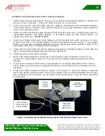
Страница 20: ...pansion anchors may not be suitable for every application It is important that you use the correct anchors for your specific needs For example if you are anchoring to a thin slab that has access underneath you may need to through bolt the unit Another example involves wooden flooring Obviously expansion anchors are not appropriate to secure a PNG to a wood floor Wood flooring may require cross bra...

Страница 21: ...t hand units as above You may Comtran Corp type 7110 or Belden 8466 12 conductor 18AWG See the section 4 1 Low Voltage Cables You may also use Belden 83662 for plenum applications without metallic conduit for the low voltage interconnect UL equivalent are accepted 5 Install remote control cables if optional remote control panel is installed between control desk and right or intermediate pedestal u...

Страница 22: ...ht and flat on the ground All anchor bolts conduits and cabling should have been properly passed trough the floor at this point Check that the floor is perfectly leveled the base of the unit must be flushed with the floor Small level defect can be adjusted with shim later on However the floor must be nearly leveled for the PNG to operate properly Position the PNG on site precisely with the help of...

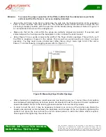
Страница 23: ...ithin the group are perfectly aligned and leveled If required add shims between the housings and the baseplate in order to make the units leveled Using Figure 18 as a guide measure the width of the finger shutter openings This will tell you if the PNG is sagging or bowed in the middle This as well as overall leveling is critical to proper operation You may need to use a bullet level rather than a ...

Страница 24: ... to third parties without written prior agreement of Automatic Systems Document subject to change without notice 24 Figure 19 Leveling the PNG If you accidentally twisted the unit during installation you may need to realign the entire frame An inability to obtain consistent measurements shown in the figure above is an indication of this If the frame is twisted out of alignment please call for spec...

Страница 25: ...distribution panel In special installations where feeding directly from a step down transformer delta wye type the center point ground of a wye transformer should be used GND The Equipment Ground must be connected to the building ground Ground impedance must conform to the requirements of national and local industrial safety regulations and all electrical codes The integrity of all ground connecti...

Страница 26: ...ntrol output to open the PNG for direction A to connection block X13 see section 2 7 AS1007 Board Interface 2 6 1 2 Location MR Master Unit Inside Rear Door Connect the motor interconnect cable high voltage interconnect into the motor junction box This junction box is marked 240 V This marking is for internal use only No external power is wired to this Only the connection cable from the slave moto...

Страница 27: ...here The incoming power is routed trough the main power junction box see section MF it is rated 120V not 240V 2 6 3 Intermediate Unit Slave Side 2 6 3 1 Location SR Slave Side Inside Rear Door Connect the motor interconnect cable coming form the master motor interconnect junction box into the slave motor interconnect junction box Respect the wire color runs See Figure 33 Make sure that you connect...

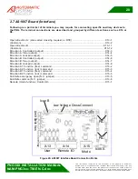
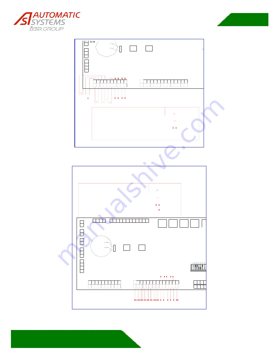
Страница 28: ...re described and grouped by different sections such as X14 or X6 Open direction A also called crossing request or RTE X13 1 Common X13 2 Open direction B X13 11 Common X13 12 Direction A Controlled output X14 3 Direction A Free output X14 4 Direction A Locked output X14 5 Direction B Controlled output X14 6 Direction B Free output X14 7 Direction B Locked output X14 8 Direction A1 Function free co...

Страница 29: ...est to enter exit direction A Card refused Dir A display red X Open Doors emergency open display Arrow both sides Passage Counter Direction A Passage Authorized Dir A reset after passage Request to enter exit Dir B LEGEND Momentary Normally Closed Dry Contact Out Normally Open Maintained Figure 21 X13 Terminals AS 1007 1 2 3 4 1 2 3 4 5 6 7 8 9 1 2 3 4 5 6 7 8 9 10 11 12 13 24v X 13 X 5 X 4 X 3 X ...
Страница 30: ...omatic Systems Document subject to change without notice 30 2 8 Wiring Principle for One Lane Hi Voltage Interconnect Low Voltage Interconnect Motor J B PUBLIC UNSECURED SIDE DIRECTION A ENTRY LoVolt Term 120VAC Motor J B From Access Sys X6 Power In JB SECURE SIDE DIRECTION B EXIT X13 Interface Board Figure 23 Wiring Principle for Single Lane Only one branch circuit of 120VAC is required Both low ...

Страница 31: ... J B X13 X6 From Access Sys X13 From Access Sys X13 Low Voltage Interconnect X6 Power In JB LoVolt Term Motor J B X6 LoVolt Term Motor J B 120VAC Hi Voltage Interconnect Motor J B Board Interface Motor J B Interface Board 120VAC Low Voltage Interconnect Hi Voltage Interconnect 120VAC LoVolt Term Motor J B Interface Board SECURE SIDE DIRECTION B EXIT Power In JB Low Voltage Interconnect PUBLIC UNSE...

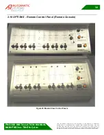
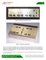
Страница 32: ...ent shall refrain from using it for any purpose other than the use of the products or the execution of the project to which it refers and from communicating it to third parties without written prior agreement of Automatic Systems Document subject to change without notice 32 2 10 OPTIONS Remote Control Panel Remote Console Figure 25 Master Slave Control Panels ...

Страница 33: ...gure 26 Rack Mount Single Control Panel Figure 27 Control Panel with Backbox Remote Control Panels are always wired to the Interface boards within the Master units in location MR In some cases such as with Master Slave or other dual control additional wires are required between the separate control panels themselves Remote consoles are special order items and are manufactured to specific layouts a...

Страница 34: ...n of the PNG gate requires the correct alignment of the photocells the infrared beam must be as best as possible centered on the corresponding reflector receiving photocell Moreover their sensitivity must be correctly adjusted so as to ensure an optimal detection level The lens of the cell must be kept clean All optical systems being influenced by the environment in which they are situated the pre...

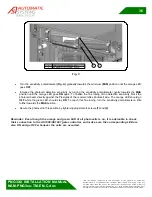
Страница 35: ...change without notice 35 Fig A The equipment must be powered and the reflectors emitter photocell and the smoked Plexiglas strip over the cells must be clean Proceed as follows to adjust the cells Set the operation selector to the L light position In this setting the photocell output stays ON when the beam of the sensor is not blocked See figure B Fig B Set the sensitivity potentiometer to the max...

Страница 36: ...e LED goes OFF Increase the photocell detection sensitivity by turning the sensitivity potentiometer gently towards the MAX position until the orange LED goes ON again To finalize the fine tuning of the detection sensitivity block the photocell beam directly against the Plexiglas of the receiver reflex photocell side The orange LED should go OFF while the green LED should stay ON To reach this fin...

Страница 37: ...INJURY OR DEATH TURN OFF THE POWER SUPPLY USING THE CIRCUIT BREAKER PRIOR TO PERFORMING THE ADJUSTMENT 3 1 2 1 Closing Limit Switch Adjustment 2 1 1 2 2 3 3 4 4 5 5 6 6 CAM LIMIT SWITCH BRACKET CLOSING LIMIT SWITCH CLS OPENING LIMIT SWITCH OLS 1 SPACER SPACER BLOCK 3 OLS CLS Figure 29 Closing Limit Switch Adjustment Step 1 3 1 Set the crank at the appropriate distance from the lower stopper For PN...

Страница 38: ...bumper 5 Move the opening limit switch bracket so that the edge of the roller bracket is lined up with the edge of the cam see line and dot on the picture Press the opening limit switch against a 0 7mm feeler gauge 6 Tighten the opening limit switch bracket screws 7 Remove the feeler gauge The limit switch lever should have a little slack Figure 31 Closing Limit Switch Adjustment Step 8 10 8 To av...

Страница 39: ...Automatic Systems Document subject to change without notice 39 3 1 2 2 Opening Limit Switch Adjustment Figure 32 Opening Limit Switch Adjustment Step 1 4 1 Block the glass in the fully open position Crank resting on the open position bumper 2 Move the opening limit switch bracket so that the edge of the roller bracket is lined up with the edge of the cam see line and dot on the picture Press the o...

Страница 40: ...ntact our technical support department 3 3 Troubleshooting 1 One of the first steps to troubleshoot newly installed units is to double check each piece of wire and its termination Miswires are a very common cause of startup trouble Also check that all plugs circuit cards and jacks are firmly seated in their respective sockets 2 If the slave motor rotates in the wrong direction turn off the main ci...

Страница 41: ...ential The recipient shall refrain from using it for any purpose other than the use of the products or the execution of the project to which it refers and from communicating it to third parties without written prior agreement of Automatic Systems Document subject to change without notice 41 4 REFERENCE 4 1 Low Voltage Cables 4 1 1 Belden 8466 ...

Страница 42: ...ems and is confidential The recipient shall refrain from using it for any purpose other than the use of the products or the execution of the project to which it refers and from communicating it to third parties without written prior agreement of Automatic Systems Document subject to change without notice 42 4 1 2 Comtran 7110 ...

Страница 43: ...fidential The recipient shall refrain from using it for any purpose other than the use of the products or the execution of the project to which it refers and from communicating it to third parties without written prior agreement of Automatic Systems Document subject to change without notice 43 4 2 Motor Interconnect Cable 4 1 1 Belden 29500 ...

Страница 44: ...matic Systems and is confidential The recipient shall refrain from using it for any purpose other than the use of the products or the execution of the project to which it refers and from communicating it to third parties without written prior agreement of Automatic Systems Document subject to change without notice 44 ...

Страница 45: ...matic Systems and is confidential The recipient shall refrain from using it for any purpose other than the use of the products or the execution of the project to which it refers and from communicating it to third parties without written prior agreement of Automatic Systems Document subject to change without notice 45 ...

Страница 46: ...idential The recipient shall refrain from using it for any purpose other than the use of the products or the execution of the project to which it refers and from communicating it to third parties without written prior agreement of Automatic Systems Document subject to change without notice 46 4 2 Belden Remote Console Cable 4 3 1 Belden 8459 ...

Страница 47: ...ems and is confidential The recipient shall refrain from using it for any purpose other than the use of the products or the execution of the project to which it refers and from communicating it to third parties without written prior agreement of Automatic Systems Document subject to change without notice 47 4 3 2 Belden 540BUE ...

Страница 48: ...ems and is confidential The recipient shall refrain from using it for any purpose other than the use of the products or the execution of the project to which it refers and from communicating it to third parties without written prior agreement of Automatic Systems Document subject to change without notice 48 4 3 3 Belden 530BUE ...

Страница 49: ...l refrain from using it for any purpose other than the use of the products or the execution of the project to which it refers and from communicating it to third parties without written prior agreement of Automatic Systems Document subject to change without notice 49 4 4 Electrical Diagram 4 4 1 Interconnect Diagram Figure 33 PNG EL 01 EN D Interconnect Wiring Diagram ...

Страница 50: ...ipient shall refrain from using it for any purpose other than the use of the products or the execution of the project to which it refers and from communicating it to third parties without written prior agreement of Automatic Systems Document subject to change without notice 50 4 4 2 Wiring Diagram Figure 34 082703 E18 EN F Power Supply Drive Wiring Diagram ...

Отзывы: