


TANK-760 Em b e d d e d S ys te m
P a g e 27
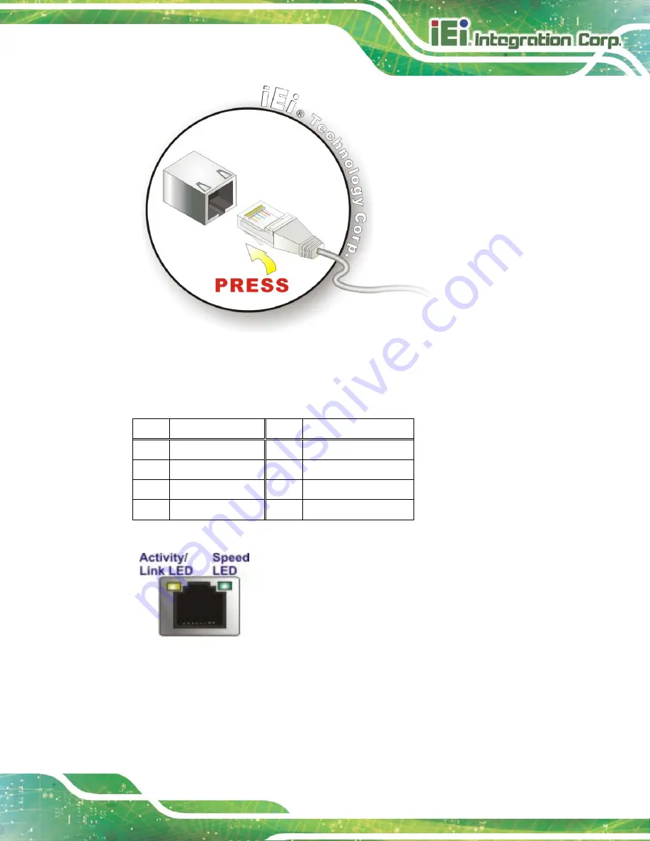
Figure 3-15: LAN Connection
S te p 3:
Insert the LAN cable RJ-45 connector.
Once aligned, gently insert the LAN
cable RJ-45 connector into the system RJ-45 connector.
Pin
Description
Pin
Description
1
MDI0+
5
MDI2+
2
MDI0-
6
MDI2-
3.
MDI1+
7
MDI3+
4.
MDI1-
8
MDI3-
Table 3-4: LAN Pinouts
Figure 3-16: RJ-45 Ethernet Connector
The RJ-45 Ethernet connector has two status LEDs, one green and one yellow. The green
LED indicates activity on the port and the yellow LED indicates the port is linked. See
Содержание TANK-760
Страница 8: ...TANK 760 Embedded Sys tem Page viii Figure 3 26 Power Button 35 ...
Страница 10: ...TANK 760 Embedded Sys tem Page 1 Chapter 1 1 Introduction ...
Страница 19: ...TANK 760 Embedded Sys tem Page 10 Chapter 2 2 Unpacking ...
Страница 23: ...TANK 760 Embedded Sys tem Page 14 Chapter 3 3 Ins tallation ...
Страница 45: ...TANK 760 Embedded Sys tem Page 36 Chapter 4 4 BIOS ...
Страница 81: ...TANK 760 Embedded Sys tem Page 72 Appendix A A Safety Precautions ...
Страница 86: ...TANK 760 Embedded Sys tem Page 77 Appendix B B Hazardous Materials Dis clos ure ...


