TANK-700-QM67W-MRAY Em b e d d e d S ys te m
P a g e 35
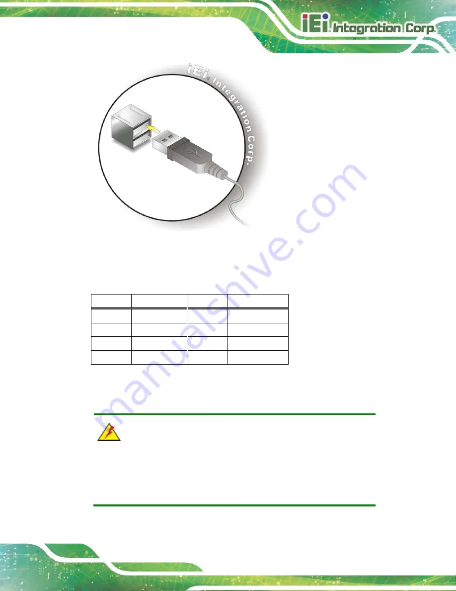
Figure 3-27: USB Device Connection
S te p 3:
Insert the device connector
. Once aligned, gently insert the USB device
connector into the on-board connector.
Pin
Description
Pin
Description
1
VCC
5
VCC
2
DATA-
6
DATA-
3
DATA+
7
DATA+
4
GROUND
8
GROUND
Table 3-12: USB Port Pinouts
3.8
P o we rin g On /Off th e S ys te m
WARNING:
Make sure a power supply with the correct input voltage is being fed into
the system. Incorrect voltages applied to the system may cause damage to
the internal electronic components and may also cause injury to the user.
Power on
the system: press the power button for 3 seconds
Содержание TANK-700-QM67W-MRAY
Страница 10: ...TANK 700 QM67W MRAY Embedded Sys tem Page 1 Chapter 1 1 Introduction ...
Страница 18: ...TANK 700 QM67W MRAY Embedded Sys tem Page 9 Chapter 2 2 Unpacking ...
Страница 22: ...TANK 700 QM67W MRAY Embedded Sys tem Page 13 Chapter 3 3 Ins tallation ...
Страница 52: ...TANK 700 QM67W MRAY Embedded Sys tem Page 43 Chapter 4 4 BIOS ...
Страница 88: ...TANK 700 QM67W MRAY Embedded Sys tem Page 79 Appendix A A Safety Precautions ...
Страница 93: ...TANK 700 QM67W MRAY Embedded Sys tem Page 84 Appendix B B Hazardous Materials Dis clos ure ...


