TANK-620-ULT3 Embedded System
Page 25
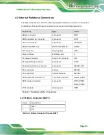
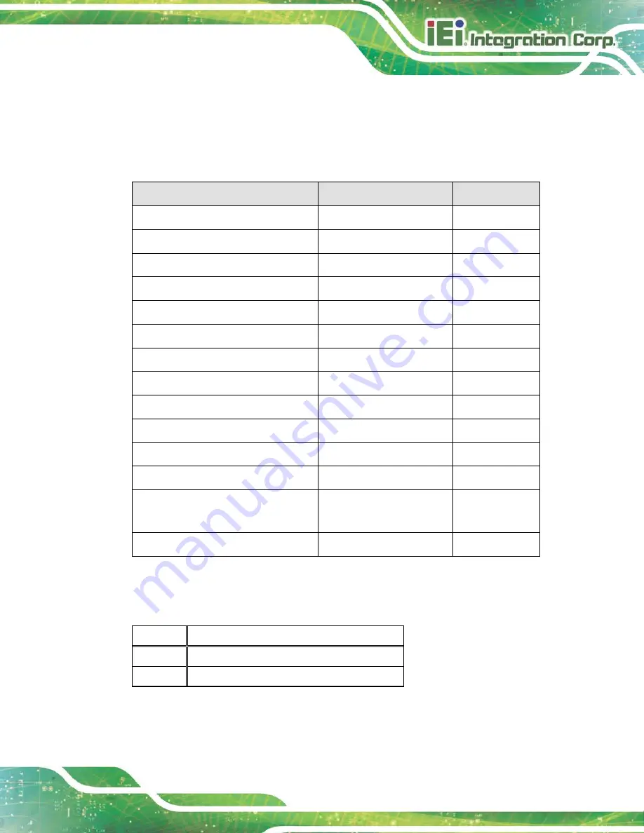
4.2 Internal Peripheral Connectors
The table below shows a list of the internal peripheral interface connectors on the system
motherboard. Pinouts of these connectors can be found in the following sections.
Connector
Type
Label
Battery connector
2-pin wafer
BAT1
BIOS programming connector
6-pin wafer
JSPI1
CPU fan connector
4-pin wafer
CPU/FAN1
DDR4 SO-DIMM slots
DDR4 SO-DIMM slot
DIMM1
LPT connector
26-pin header
LPT1
M.2 slot, M-key
M.2 M-key slot
J1
EC debug connector
20-pin FPC connector
CN1
EC programming connector
6-pin wafer
JSPI2
Keyboard and mouse connector
6-pin wafer
KB_MS_CN1
PCIe mini Card
Full size
MPCIE1
PCIe mini Card
Full size/Half size
MPCIE2
SATA 6Gb/s drive connectors
7-pin SATA connector
SATA1, SATA2
SATA power connectors
2-pin wafer
SATA_PWR1,
SATA_PWR2
TPM connector
20-pin header
TPM1
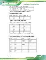
Table 4-1: Peripheral Interface Connectors
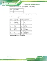
4.2.1 Battery Connector (BAT1)
PIN NO.
DESCRIPTION
1
VBATT
2
GND
Table 4-2: Battery Connector Pinouts (BAT1)
Содержание TANK-620-ULT3
Страница 12: ...TANK 620 ULT3 Embedded System Page 1 Chapter 1 1 Introduction ...
Страница 19: ...TANK 620 ULT3 Embedded System Page 8 Chapter 2 2 Unpacking ...
Страница 23: ...TANK 620 ULT3 Embedded System Page 12 Chapter 3 3 Installation ...
Страница 34: ...TANK 620 ULT3 Embedded System Page 23 4 System Motherboard Chapter 4 ...
Страница 47: ...TANK 620 ULT3 Embedded System Page 36 Chapter 5 5 BIOS ...
Страница 94: ...TANK 620 ULT3 Embedded System Page 83 Appendix A A Regulatory Compliance ...
Страница 99: ...TANK 620 ULT3 Embedded System Page 88 Appendix B B BIOS Options ...
Страница 103: ...TANK 620 ULT3 Embedded System Page 92 Appendix C C Terminology ...
Страница 107: ...TANK 620 ULT3 Embedded System Page 96 Appendix D D Safety Precautions ...
Страница 112: ...TANK 620 ULT3 Embedded System Page 101 Appendix E E Digital I O Interface ...
Страница 115: ...TANK 620 ULT3 Embedded System Page 104 Appendix F F Hazardous Materials Disclosure ...

