
TANK-620-ULT3 Embedded System
Page 24
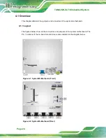
4.1 Overview
This chapter details all the jumpers and connectors of the system motherboard.
4.1.1 Layout
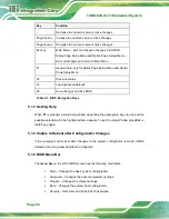
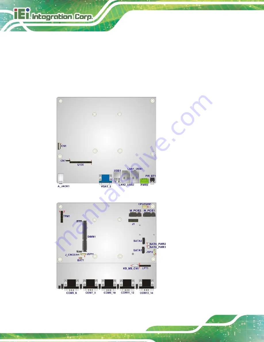
The figures below show all the connectors and jumpers of the system motherboard. The
Pin 1 locations of the on-board connectors are also indicated in the diagram below.
Figure 4-1: System Motherboard (Front)
Figure 4-2: System Motherboard (Rear)
Содержание TANK-620-ULT3
Страница 12: ...TANK 620 ULT3 Embedded System Page 1 Chapter 1 1 Introduction ...
Страница 19: ...TANK 620 ULT3 Embedded System Page 8 Chapter 2 2 Unpacking ...
Страница 23: ...TANK 620 ULT3 Embedded System Page 12 Chapter 3 3 Installation ...
Страница 34: ...TANK 620 ULT3 Embedded System Page 23 4 System Motherboard Chapter 4 ...
Страница 47: ...TANK 620 ULT3 Embedded System Page 36 Chapter 5 5 BIOS ...
Страница 94: ...TANK 620 ULT3 Embedded System Page 83 Appendix A A Regulatory Compliance ...
Страница 99: ...TANK 620 ULT3 Embedded System Page 88 Appendix B B BIOS Options ...
Страница 103: ...TANK 620 ULT3 Embedded System Page 92 Appendix C C Terminology ...
Страница 107: ...TANK 620 ULT3 Embedded System Page 96 Appendix D D Safety Precautions ...
Страница 112: ...TANK 620 ULT3 Embedded System Page 101 Appendix E E Digital I O Interface ...
Страница 115: ...TANK 620 ULT3 Embedded System Page 104 Appendix F F Hazardous Materials Disclosure ...


