IEI Technology SBOX-100-QM87i Скачать руководство пользователя страница 79


SBOX-100-QM87i Fanless Marine Computer 

Page 67

Step 3: 

Remove the cable tie that secures the heatsink with the SO-DIMM. Then, 

remove the heatsink.   
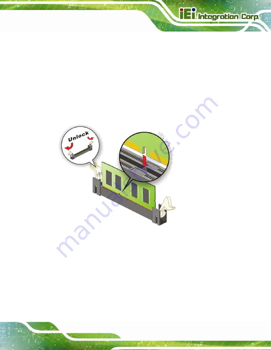
Step 4: 

Release the arms on the SO-DIMM socket to remove the SO-DIMM.   

Step 5: 

Align the new SO-DIMM with the socket. The SO-DIMM must be oriented in 

such a way that the notch in the middle of the SO-DIMM must be aligned with 

the plastic bridge in the socket (

85

Figure 5-3

). 

Step 6: 

Press the SO-DIMM down until the arms of the SO-DIMM socket clip into place 

and secure the SO-DIMM in the socket (

85

Figure 5-3

). 


Figure 5-3: SO-DIMM Installation 

Step 7: 

Place the heatsink and use a cable tie to secure the heatsink with the SO-DIMM.   

Step 8: 

Reinstall the bottom cover. 

Step 0:


Содержание SBOX-100-QM87i

Страница 1: ... I User Manual Fanless Marine Computer with Intel Core i5 4400E Dual Core CPU Intel QM87 Express Chipset GbE LAN HDMI DVI D VGA CAN Bus CFast Slot RS 232 422 485 USB 2 0 USB 3 0 iRIS 2400 RoHS Compliant MODEL SBOX 100 QM87i Rev 1 00 June 4 2015 ...

Страница 2: ...SBOX 100 QM87i Fanless Marine Computer Page II Revision Date Version Changes June 4 2015 1 00 Initial release ...

Страница 3: ...al damages arising out of the use or inability to use the product or documentation even if advised of the possibility of such damages This document contains proprietary information protected by copyright All rights are reserved No part of this manual may be reproduced by any mechanical electronic or other means in any form without prior written permission of the manufacturer TRADEMARKS All registe...

Страница 4: ...ALLATION PRECAUTIONS 13 3 1 1 High Surface Temperature 13 3 2 CFAST CARD INSTALLATION 14 3 3 HDD INSTALLATION 15 3 4 AT ATX MODE SELECTION 17 3 5 MOUNTING THE SYSTEM 17 3 6 SERIAL DEVICE CONNECTION 18 3 6 1 RS 232 Serial Port COM1 19 3 6 2 RS 232 422 485 Serial Port COM2 COM5 19 3 7 CAN BUS CONNECTION AND CONFIGURATION 20 3 8 POWERING ON THE SYSTEM 21 3 9 CLEAR CMOS 22 3 10 DRIVER INSTALLATION 22 ...

Страница 5: ...ation 39 4 3 8 USB Configuration 40 4 3 9 iWDD H W Monitor 41 4 3 10 F81866 Super IO Configuration 42 4 3 10 1 Serial Port n Configuration 43 4 3 11 Serial Port Console Redirection 48 4 3 12 IEI Feature 50 4 4 CHIPSET 51 4 4 1 PCH IO Configuration 51 4 4 2 System Agent SA Configuration 53 4 4 2 1 Graphics Configuration 54 4 4 3 Memory Configuration 56 4 5 BOOT 56 4 6 SECURITY 58 4 7 SAVE EXIT 59 4...

Страница 6: ...6 2 11 Power Connector PWR1 75 6 2 12 Power Button Connector PWR_BTN1 76 6 2 13 PS_ON Connector PS_ON1 76 6 2 14 RS 232 422 485 Connector COM2 COM3 COM4 COM5 76 6 2 15 SATA Connector S_ATA1 76 6 2 16 SATA Connector S_ATA2 77 6 2 17 SATA Power Connector SATA_PWR1 77 6 2 18 SATA Power Connector SATA_PWR2 78 6 2 19 SMBus Connector EC SMB1 78 6 2 20 SPI Flash Connector SPI1 78 6 2 21 SPI Flash Connect...

Страница 7: ... Precautions 91 B 1 3 Product Disposal 92 B 2 MAINTENANCE AND CLEANING PRECAUTIONS 92 B 2 1 Maintenance and Cleaning 92 B 2 2 Cleaning Tools 93 C BIOS MENU OPTIONS 94 C 1 BIOS CONFIGURATION OPTIONS 95 D WATCHDOG TIMER 97 E HAZARDOUS MATERIALS DISCLOSURE 100 E 1 HAZARDOUS MATERIAL DISCLOSURE TABLE FOR IPB PRODUCTS CERTIFIED AS ROHS COMPLIANT UNDER 2002 95 EC WITHOUT MERCURY 101 ...

Страница 8: ... 3 6 Installing the HDD 16 Figure 3 7 AT ATX Mode Selection 17 Figure 3 8 Mounting Brackets 17 Figure 3 9 Serial Port Locations 18 Figure 3 10 CAN Bus Connector 20 Figure 3 11 CAN Bus Jumper Locations 21 Figure 3 12 Power Input Connector Pinouts 21 Figure 3 13 Power Connector and Power Button 22 Figure 3 14 Clear CMOS Button Location 22 Figure 3 15 IEI iMAN Web Address 24 Figure 3 16 IEI iMAN Web ...

Страница 9: ...onnector CPU_FAN1 Pinouts 73 Table 6 8 Front Panel Connector F_PANEL1 Pinouts 74 Table 6 9 IPMI LED Connector IPMI_LED1 Pinouts 74 Table 6 10 LAN Active LED Connector LAN_ACT_LED1 74 Table 6 11 PCIe Mini Slots MINI PCIE1 MINI PCIE2 Pinouts 75 Table 6 12 Power Connector PWR1 Pinouts 75 Table 6 13 Power Button Connector PWR_BTN1 Pinouts 76 Table 6 14 PS_ON Connector PS_ON1 Pinouts 76 Table 6 15 RS 2...

Страница 10: ...VI Connector DVI Pinouts 80 Table 6 27 VGA Connector VGA1 Pinouts 81 Table 6 28 HDMI Connector HDMI1 Pinouts 81 Table 6 29 RJ 45 GbE Connector LAN1 2 CN1 Pinouts 82 Table 6 30 RS 232 Serial Port COM1 Pinouts 82 Table 6 31 USB 2 0 Connector USB1 Pinouts 82 Table 6 32 USB 3 0 Connector USB3_CN1 Pinouts 83 ...

Страница 11: ...uration 40 BIOS Menu 11 iWDD H W Monitor 41 BIOS Menu 12 F81866 Super IO Configuration 42 BIOS Menu 13 Serial Port n Configuration Menu 43 BIOS Menu 14 Serial Port Console Redirection 49 BIOS Menu 15 IEI Feature 50 BIOS Menu 16 Chipset 51 BIOS Menu 17 PCH IO Configuration 51 BIOS Menu 18 System Agent SA Configuration 53 BIOS Menu 19 Graphics Configuration 54 BIOS Menu 20 Memory Configuration 56 BI...

Страница 12: ......

Страница 13: ...SBOX 100 QM87i Fanless Marine Computer Page 1 Chapter 1 1 Introduction ...

Страница 14: ...e IT resource save time and manage multiple systems The SBOX 100 QM87i supports IPMI 2 0 through the optional iRIS 2400 module The SBOX 100 QM87i has five serial ports including four RS 232 422 485 serial ports on the front panel and one RS 232 serial port on the rear panel The HDMI DVI D and VGA connectors allow the SBOX 100 QM87i to support various display devices Other slots and connectors incl...

Страница 15: ...he SBOX 100 QM87i provides access to the following external I O connectors and LED indicators 4 x RS 232 422 485 serial port 1 x Power LED indicator on green off amber 1 x HDD CFast card LED indicator active blinking in red 1 x IPMI LED indicator enabled blue disabled off 2 x Knockout hole for SMA antenna connector Figure 1 2 Front Panel NOTE The default settings for COM2 COM5 are set to RS 485 To...

Страница 16: ...io line in jack 1 x Audio line out jack 1 x Audio mic in jack 1 x AT ATX power mode switch 2 x CAN bus terminal block 1 x CFast card slot 1 x Clear CMOS switch 1 x DVI D connector 2 x GbE RJ 45 connector 1 x HDMI connector 1 x Keyboard Mouse PS 2 connector 1 x Power button 1 x RS 232 DB 9 serial port 2 x USB 2 0 port connector 2 x USB 3 0 port connector 1 x VGA connector Figure 1 3 Rear Panel ...

Страница 17: ...ax 16 GB Ethernet Two GbE LAN RJ 45 connectors with teaming support and 2 kV isolation protection LAN1 Intel I217 LM with Intel AMT 9 0 support LAN2 Intel I210 AT Ethernet controller CAN Bus 2 x CAN bus 2 0B terminal block 3 pin with 2 5 kV isolation protection Display 1 x DVI D connector 1 x HDMI connector 1 x VGA connector Serial Port 1 x RS 232 DB 9 serial port non isolated 4 x RS 232 422 485 D...

Страница 18: ...er Input Isolated 18 V 36 V DC 8 A 4 A max via 3 pin terminal block Power Supply 150 W DC input ATX power supply module preinstalled Chassis Construction Aluminum Alloy top cover with heavy duty metal Mounting Wall mounting Watchdog Timer Supporting 1 255 levels for time interval system reset Operating Temperature 15ºC 55ºC Storage Temperature 20 ºC 60ºC Operating Humidity 5 95 Color Black Weight ...

Страница 19: ...SBOX 100 QM87i Fanless Marine Computer Page 7 1 6 Dimensions The physical dimensions of the SBOX 100 QM87i are shown in 64Figure 1 4 Figure 1 4 SBOX 100 QM87i Dimensions mm ...

Страница 20: ...SBOX 100 QM87i Fanless Marine Computer Page 8 Chapter 2 2 Unpacking ...

Страница 21: ...static wristband Wearing a simple anti static wristband can help to prevent ESD from damaging the board Self grounding Before handling the board touch any grounded conducting material During the time the board is handled frequently touch any conducting materials that are connected to the ground Use an anti static pad When configuring the SBOX 100 QM87i place it on an anti static pad This reduces t...

Страница 22: ...or you purchased the SBOX 100 QM87i from or contact an IEI sales representative directly To contact an IEI sales representative please send an email to sales ieiworld com The SBOX 100 QM87i is shipped with the following components Quantity Item Image 1 SBOX 100 QM87i marine computer 1 Keyboard and mouse Y cable P N 32006 000300 100 RS 4 Screws for foot pad installation 8 Screws silver 4 Foot pads ...

Страница 23: ...SBOX 100 QM87i Fanless Marine Computer Page 11 1 One Key Recovery CD Table 2 1 Package List Contents ...

Страница 24: ...SBOX 100 QM87i Fanless Marine Computer Page 12 Chapter 3 3 Installation ...

Страница 25: ...only be carried out by qualified personnel who are familiar with the associated dangers Air Circulation Make sure there is sufficient air circulation when installing the SBOX 100 QM87i The SBOX 100 QM87i s cooling vents must not be obstructed by any objects Blocking the vents can cause overheating of the SBOX 100 QM87i Leave at least 5 cm of clearance around the SBOX 100 QM87i to prevent overheati...

Страница 26: ...lock and key or other means of security and is controlled by the authority responsible for the location 3 2 CFast Card Installation The SBOX 100 QM87i series has a CFast card slot on the rear panel To install the CFast card into the system please follow the steps below Step 1 Locate the CFast card slot on the rear panel Remove the CFast slot cover retention screw on the rear panel Figure 3 1 Figur...

Страница 27: ...D bays inside the bottom cover To install HDDs follow the steps below Step 1 Remove the bottom cover by removing the 11 retention screws on the bottom panel See Figure 3 3 Figure 3 3 Bottom Cover Retention Screws Step 2 Locate the HDD brackets inside the bottom cover Remove the four HDD bracket retention screws of one of the HDD brackets and lift the HDD bracket Figure 3 4 HDD Bracket Retention Sc...

Страница 28: ...screws two screws on each side See Figure 3 5 Figure 3 5 Inserting the HDD Step 4 Install the HDD bracket in the same position it was before Figure 3 6 Installing the HDD Step 5 Repeat the steps described above to install another HDD if necessary Step 6 Connect the SATA cables and the SATA power cables to the motherboard Step 7 Reinstall the bottom cover with the previously removed retention screw...

Страница 29: ...l The switch is shown below Figure 3 7 AT ATX Mode Selection 3 5 Mounting the System The mounting brackets on both sides of the SBOX 100 QM87i allow it to be mounted onto a wall or some other surface To mount the system align the mounting holes in the mounting brackets with the holes in the mounting surface Then insert retention screws in each bracket to secure the system to the surface Figure 3 8...

Страница 30: ...RS 232 port on the rear panel The port locations are shown in Figure 3 9 The pinouts of the serial ports are listed in the following sections Figure 3 9 Serial Port Locations NOTE The default settings for COM2 COM5 are set to RS 485 To configure the COM port mode please change the BIOS options in Advanced F81866 Super IO Configuration Serial Port Configuration refer to Section 4 3 10 1 ...

Страница 31: ...Pinouts 3 6 2 RS 232 422 485 Serial Port COM2 COM5 The RS 232 422 485 mode selection of COM2 COM5 is made through the system BIOS Please refer to Section 4 3 10 1 for selecting COM port mode The default setting for COM2 COM5 is RS 485 The RS 232 422 485 serial port pinouts are listed in the following table PIN NO RS 232 RS 422 RS 485 1 DCD TXD422 TXD485 2 RXD TXD422 TXD485 3 TXD RXD422 4 DTR RXD42...

Страница 32: ...he pinouts for the CAN bus connector are listed in the figure and table below Figure 3 10 CAN Bus Connector PIN NO DESCRIPTION PIN NO DESCRIPTION 1 CAN1H 2 CAN2H 3 CAN1L 4 CAN2L 5 GND_CAN1 6 GND_CAN2 Table 3 3 CAN Bus Connector Pinouts The on board jumpers JP1 and JP2 can be used for CAN bus configuration The jumper settings and locations are listed below ...

Страница 33: ...le 3 4 CAN Bus Jumper Settings 3 8 Powering On the System To power on the system follow the steps below Step 1 Connect the power cable to the 3 pin power input terminal block The pinouts of the power input connectors are shown below Figure 3 12 Power Input Connector Pinouts Step 2 Push the power button on the I O panel to power on the system Step 0 ...

Страница 34: ... the system BIOS information To do this push the clear CMOS button for three seconds and then restart the system The clear CMOS button location is shown in Figure 3 14 Figure 3 14 Clear CMOS Button Location 3 10 Driver Installation NOTE The content of the CD may vary throughout the life cycle of the product and is subject to change without prior notice Visit the IEI website or contact technical su...

Страница 35: ...AN bus ME USB 3 0 The following drivers can be installed on the Windows 8 operating system Chipset Graphics LAN Audio CAN bus ME 3 11 IPMI Setup Procedure The SBOX 100 QM87i with iRIS 2400 module installed features Intelligent Platform Management Interface IPMI that helps lower the overall costs of server management by enabling users to maximize IT resources save time and manage multiple systems T...

Страница 36: ...ess of the managed system It is recommended to use the IPMI Tool on the managed system to obtain the IP address To use IPMI Tool to obtain IP address follow the steps below a Copy the Ipmitool exe file to a bootable USB flash drive b Insert the USB flash drive to the SBOX 100 QM87i c The SBOX 100 QM87i boots from the USB flash drive d Enter the following command ipmitool 20 30 02 01 03 00 00 there...

Страница 37: ...rname admin Password admin Step 5 Press the login button to login the system Step 6 The IEI iMAN Web Interface appears S t e p 0 Figure 3 16 IEI iMAN Web GUI NOTE To understand how to use the IEI iMAN Web GUI please refer to the iRIS 2400 Web GUI user manual in the utility CD came with the SBOX 100 QM87i The user manual describes each function in detail ...

Страница 38: ...SBOX 100 QM87i Fanless Marine Computer Page 26 Chapter 4 4 BIOS Setup ...

Страница 39: ...ys 1 Press the DEL or F2 key as soon as the system is turned on or 2 Press the DEL or F2 key when the Press DEL or F2 to enter SETUP message appears on the screen 0 If the message disappears before the DEL or F2 key is pressed restart the computer and try again 4 1 2 Using Setup Use the arrow keys to highlight items press ENTER to select use the PageUp and PageDown keys to change entries press F1 ...

Страница 40: ...etting Help When F1 is pressed a small help window describing the appropriate keys to use and the possible selections for the highlighted item appears To exit the Help Window press ESC or the F1 key again 4 1 4 BIOS Menu Bar The menu bar on top of the BIOS screen has the following main items Main Changes the basic system configuration Advanced Changes the advanced system settings Chipset Changes t...

Страница 41: ...l R Core TM i5 440 Frequency 3200 MHz Processor ID 306c3 Stepping C0 Number of Processors 2Core S 4Thread s Microcode Revision 1c GT Info GT2 800 MHz IGF VBIOS Version 2167 Memory RC Version 1 6 2 1 Total Memory 4096 MB DDR3 Memory Frequency 1600 Mhz PCH Information Name LynxPoint PCH SKU QM87 Stepping 05 C2 LAN PHY Revision A3 ME FW Version 9 1 10 1005 ME Firmware SKU 5MB SPI Clock Frequency D0FR...

Страница 42: ... below may cause the system to malfunction Make sure that the settings made are compatible with the hardware Aptio Setup Utility Copyright C 2012 American Megatrends Inc Main Advanced Chipset Boot Security Save Exit Server Mgmt ACPI Settings RTC Wake Settings Trusted Computing CPU Configuration SATA Configuration Intel R Rapid Start Technology AMT Configuration USB Configuration iWDD H M Monitor F...

Страница 43: ...elp F2 Previous Values F3 Optimized Defaults F4 Save ESC Exit Version 2 15 1236 Copyright C 2012 American Megatrends Inc BIOS Menu 3 ACPI Configuration ACPI Sleep State S1 only CPU Stop Clock Use the ACPI Sleep State option to specify the sleep state the system enters when it is not being used S1 only CPU Stop Clock DEFAULT The system enters S1 POS sleep state The system appears off The CPU is sto...

Страница 44: ...en enabled System will wake on the dat hr min sec specified Select Screen Select Item EnterSelect Change Opt F1 General Help F2 Previous Values F3 Optimized Defaults F4 Save ESC Exit Version 2 15 1236 Copyright C 2012 American Megatrends Inc BIOS Menu 4 RTC Wake Settings Wake System with Fixed Time Disabled Use the Wake System with Fixed Time option to specify the time the system should be roused ...

Страница 45: ...d to the Trusted Computing Group TCG Trusted Platform Module TPM Aptio Setup Utility Copyright C 2012 American Megatrends Inc Advanced Configuration Security Device Support Disable Current Status Information NO Security Device Found Enables or Disables BIOS support for security device O S will not show Security Device TCG EFI protocol and INT1A interface will not be available Select Screen Select ...

Страница 46: ...x Technology Supported Intel SMX Technology Supported 64 bit Supported EIST Technology Supported L1 Data Cache 32 kB x 2 L1 Code Cache 32 kB x 2 L2 Cache 256 kB x 2 L3 Cache 3072 kB Hyper threading Enbaled Active Processor cores All Intel Virtualization Technology Disabled EIST Enabled Intel TXT LT Support Disabled Enable for Windows XP and Linux OS optimized for Hyper Threading Technology and Dis...

Страница 47: ... if 64 bit OS is supported by the CPU EIST Technology Indicates if EIST Technology is supported by the CPU L1 Data Cache Lists the amount of data storage space on the L1 cache L1 Code Cache Lists the amount of code storage space on the L1 cache L2 Cache Lists the amount of storage space on the L2 cache L3 Cache Lists the amount of storage space on the L3 cache Hyper threading Disabled Use the Hype...

Страница 48: ...T Disable Intel Virtualization Technology Enabled Enable Intel Virtualization Technology EIST Enabled Use the EIST option to enable or disable the Enhanced Intel SpeedStep Technology EIST Disabled Disable Enhanced Intel SpeedStep Technology Enabled DEFAULT Enable Enhanced Intel SpeedStep Technology Intel TXT LT Support Disabled Use the Intel TXT LT Support option to enable or disable the Intel Tru...

Страница 49: ...nterSelect Change Opt F1 General Help F2 Previous Values F3 Optimized Defaults F4 Save ESC Exit Version 2 15 1236 Copyright C 2012 American Megatrends Inc BIOS Menu 7 SATA Configuration SATA Controller s Enabled Use the SATA Controller s option to configure the SATA controller s Enabled DEFAULT Enable the on board SATA controller s Disabled Disable the on board SATA controller s SATA Mode Selectio...

Страница 50: ...le Intel R Rapid Start Technology Select Screen Select Item EnterSelect Change Opt F1 General Help F2 Previous Values F3 Optimized Defaults F4 Save ESC Exit Version 2 15 1236 Copyright C 2012 American Megatrends Inc BIOS Menu 8 Intel Rapid Start Technology Intel R Rapid Start Technology Disabled Use the Intel R Rapid Start Technology option to disable or enable Intel Rapid Start Technology Disable...

Страница 51: ... extension execution If enabled this requires additional firmware in the SPI device Select Screen Select Item EnterSelect Change Opt F1 General Help F2 Previous Values F3 Optimized Defaults F4 Save Exit ESC Exit Version 2 15 1236 Copyright C 2012 American Megatrends Inc BIOS Menu 9 AMT Configuration Intel AMT Enabled Use Intel AMT option to enable or disable the Intel Active Management Technology ...

Страница 52: ...Select Item EnterSelect Change Opt F1 General Help F2 Previous Values F3 Optimized Defaults F4 Save Exit ESC Exit Version 2 15 1236 Copyright C 2012 American Megatrends Inc BIOS Menu 10 USB Configuration USB Devices The USB Devices Enabled field lists the USB devices that are enabled on the system Legacy USB Support Enabled Use the Legacy USB Support BIOS option to enable USB mouse and USB keyboar...

Страница 53: ...c Advanced PC Health Status CPU Temperature 72 C System temperature 48 C CPU_CORE 1 403 V 5V 5 014 V 12V 11 771 V DDR 1 560 V 5VSB 5 044 V 3 3V 3 323 V 3 3VSB 3 291 V Select Screen Select Item EnterSelect Change Opt F1 General Help F2 Previous Values F3 Optimized Defaults F4 Save Exit ESC Exit Version 2 15 1236 Copyright C 2012 American Megatrends Inc BIOS Menu 11 iWDD H W Monitor H W Monitor The ...

Страница 54: ...ds Inc Advanced F81866 Super IO Configuration F81866 Super IO Chip F81866 Serial Port 1 Configuration Serial Port 2 Configuration Serial Port 3 Configuration Serial Port 4 Configuration Serial Port 5 Configuration Set Parameters of Serial Port 1 COMA Select Screen Select Item EnterSelect Change Opt F1 General Help F2 Previous Values F3 Optimized Defaults F4 Save ESC Exit Version 2 15 1236 Copyrigh...

Страница 55: ...Values F3 Optimized Defaults F4 Save ESC Exit Version 2 15 1236 Copyright C 2012 American Megatrends Inc BIOS Menu 13 Serial Port n Configuration Menu 4 3 10 1 1 Serial Port 1 Configuration Serial Port Enabled Use the Serial Port option to enable or disable the serial port Disabled Disable the serial port Enabled DEFAULT Enable the serial port Change Settings Auto Use the Change Settings option to...

Страница 56: ...rt option to enable or disable the serial port Disabled Disable the serial port Enabled DEFAULT Enable the serial port Change Settings Auto Use the Change Settings option to change the serial port IO port address and interrupt address Auto DEFAULT The serial port IO port address and interrupt address are automatically detected IO 2F8h IRQ 3 Serial Port I O port address is 2F8h and the interrupt ad...

Страница 57: ... Use the Serial Port option to enable or disable the serial port Disabled Disable the serial port Enabled DEFAULT Enable the serial port Change Settings Auto Use the Change Settings option to change the serial port IO port address and interrupt address Auto DEFAULT The serial port IO port address and interrupt address are automatically detected IO 3E8h IRQ 11 Serial Port I O port address is 3E8h a...

Страница 58: ...LT Configure Serial Port 3 as RS 485 4 3 10 1 4 Serial Port 4 Configuration Serial Port Enabled Use the Serial Port option to enable or disable the serial port Disabled Disable the serial port Enabled DEFAULT Enable the serial port Change Settings Auto Use the Change Settings option to change the serial port IO port address and interrupt address Auto DEFAULT The serial port IO port address and int...

Страница 59: ...e RS232 Configure Serial Port 4 as RS 232 RS422 Configure Serial Port 4 as RS 422 RS485 DEFAULT Configure Serial Port 4 as RS 485 4 3 10 1 5 Serial Port 5 Configuration Serial Port Enabled Use the Serial Port option to enable or disable the serial port Disabled Disable the serial port Enabled DEFAULT Enable the serial port Change Settings Auto Use the Change Settings option to change the serial po...

Страница 60: ...ort address is 2D8h and the interrupt address is IRQ10 11 Serial Port Mode RS485 Use the Serial Port Mode option to set the Serial Port 5 signaling mode RS232 Configure Serial Port 5 as RS 232 RS422 Configure Serial Port 5 as RS 422 RS485 DEFAULT Configure Serial Port 5 as RS 485 4 3 11 Serial Port Console Redirection The Serial Port Console Redirection menu BIOS Menu 14 allows the console redirec...

Страница 61: ...ettings COM6 BMC Disabled Console Redirection Port Is Disabled iAMT SOL COM7 Pci Bus0 Dev0 Func0 Disabled Console Redirection Port Is Disabled Console Redirection Enable Disable Select Screen Select Item EnterSelect Change Opt F1 General Help F2 Previous Values F3 Optimized Defaults F4 Save ESC Exit Version 2 15 1236 Copyright C 2012 American Megatrends Inc BIOS Menu 14 Serial Port Console Redirec...

Страница 62: ...n when OS crashes Please install Auto Recovery API service before enabling this funciton Select Screen Select Item EnterSelect Change Opt F1 General Help F2 Previous Values F3 Optimized Defaults F4 Save ESC Exit Version 2 15 1236 Copyright C 2012 American Megatrends Inc BIOS Menu 15 IEI Feature Auto Recovery Function Disabled Use the Auto Recovery Function BIOS option to enable or disable the auto...

Страница 63: ...atrends Inc BIOS Menu 16 Chipset 4 4 1 PCH IO Configuration Use the PCH IO Configuration menu BIOS Menu 17 to configure the PCH IO chipset Aptio Setup Utility Copyright C 2012 American Megatrends Inc Chipset Auto Power Button Status Disable ATX Azalia HD Audio Enabled Serial IRQ Mode Continuous Power Saving Function ERP Disabled Control Detection of the Azalia device Disabled Azalia will be uncond...

Страница 64: ...High Definition Audio controller automatically detected and enabled Serial IRQ Mode Continuous Use the Serial IRQ Mode option to configure serial IRQ mode for serial interrupts Configuration options are listed below Quiet Continuous DEFAULT Power Saving Function ERP Disabled Use the Power Saving Function ERP option to enable or disable the power saving function Disabled DEFAULT Disable the power s...

Страница 65: ... Supported VT d Disabled Graphics Configuration Memory Configuration Check to enable VT d function on MCH Select Screen Select Item EnterSelect Change Opt F1 General Help F2 Previous Values F3 Optimized Defaults F4 Save Exit ESC Exit Version 2 15 1236 Copyright C 2012 American Megatrends Inc BIOS Menu 18 System Agent SA Configuration VT d Disabled Use the VT d option to enable or disable VT d supp...

Страница 66: ...t Change Opt F1 General Help F2 Previous Values F3 Optimized Defaults F4 Save Exit ESC Exit Version 2 15 1236 Copyright C 2012 American Megatrends Inc BIOS Menu 19 Graphics Configuration Primary Display Auto Use the Primary Display option to select the graphics controller used as the primary boot device Configuration options are listed below Auto Default IGFX PCIE DVMT Pre Allocated 256M Use the D...

Страница 67: ...otal graphic memory size used by the internal graphic device The following options are available 128M 256M MAX DEFAULT Primary IGFX Boot Display VBIOS Default Use the Primary IGFX Boot Display option to select the display device used by the system when it boots Configuration options are listed below VBIOS Default DEFAULT CRT DVI HDMI 1 Display port 1 ...

Страница 68: ...2 15 1236 Copyright C 2012 American Megatrends Inc BIOS Menu 20 Memory Configuration 4 5 Boot Use the Boot menu BIOS Menu 21 to configure system boot options Aptio Setup Utility Copyright C 2012 American Megatrends Inc Main Advanced Chipset Boot Security Save Exit Server Mgmt Boot Configuration Bootup NumLock State On Quiet Boot Enabled Option ROM Messages Force BIOS Launch PXE OpROM Disabled UEFI...

Страница 69: ...is lit Off Does not enable the keyboard Number Lock automatically To use the 10 keys on the keyboard press the Number Lock key located on the upper left hand corner of the 10 key pad The Number Lock LED on the keyboard lights up when the Number Lock is engaged Quiet Boot Enabled Use the Quiet Boot BIOS option to select the screen display when the system boots Disabled Normal POST messages displaye...

Страница 70: ...oot Security Save Exit Server Mgmt Password Description If ONLY the Administrator s password is set then this only limits access to Setup and is only asked for when entering Setup If ONLY the User s password is set then this is a power on password and must be entered to boot or enter Setup In Setup the User will have Administrator rights The password length must be in the following range Minimum l...

Страница 71: ...ystem after saving the changes Select Screen Select Item EnterSelect Change Opt F1 General Help F2 Previous Values F3 Optimized Defaults F4 Save Exit ESC Exit Version 2 15 1236 Copyright C 2012 American Megatrends Inc BIOS Menu 23 Save Exit Save Changes and Reset Use the Save Changes and Reset option to save the changes made to the BIOS options and reset the system Discard Changes and Reset Use th...

Страница 72: ...ver Mgmt menu BIOS Menu 24 to configure BMC network parameters Aptio Setup Utility Copyright C 2012 American Megatrends Inc Main Advanced Chipset Boot Security Save Exit Server Mgmt BMC Self Test Status FAILED System Event Log BMC network configuration Configure BMC network parameters Select Screen Select Item EnterSelect Change Opt F1 General Help F2 Previous Values F3 Optimized Defaults F4 Save ...

Страница 73: ...ed Change this to enable or disable all features of System Event Logging during boot Select Screen Select Item EnterSelect Change Opt F1 General Help F2 Previous Values F3 Optimized Defaults F4 Save Exit ESC Exit Version 2 15 1236 Copyright C 2012 American Megatrends Inc BIOS Menu 25 System Event Log SEL Components Enabled Use the SEL Components option to enable or disable all features of System E...

Страница 74: ...ing DEFAULT Do not do anything when SEL is full Erase Immediately Erase SEL immediately when SEL is full Log EFI Status Codes Both Use the Log EFI Status Codes option to configure how to log Extensible Firmware Interface EFI status codes Disabled DEFAULT Disable the logging of EFI status codes Both Log both error codes and progress codes Error code Log error codes only Progress code Log progress c...

Страница 75: ...pecified option will not modify any BMC network parameters during BIOS phase Select Screen Select Item EnterSelect Change Opt F1 General Help F2 Previous Values F3 Optimized Defaults F4 Save Exit ESC Exit Version 2 15 1236 Copyright C 2012 American Megatrends Inc BIOS Menu 26 BMC Network Configuration Configuration Address source Unspecified Use the Configuration Address source option to configure...

Страница 76: ...SBOX 100 QM87i Fanless Marine Computer Page 64 Chapter 5 5 Maintenance ...

Страница 77: ...y and system damage To preserve the working integrity of the SBOX 100 QM87i the system must be properly maintained If internal components need replacement the proper maintenance procedures must be followed to ensure the system can continue to operate normally 5 2 SO DIMM Replacement Procedure WARNING Users are not advised to attempt to repair or replace any internal or external components of the S...

Страница 78: ...se make sure the purchased SO DIMM complies with the memory specifications of the SBOX 100 QM87i To replace a SO DIMM into a SO DIMM socket please follow the steps below Step 1 Remove the bottom cover by removing the 11 retention screws Figure 5 1 Bottom Cover Retention Screws Step 2 Locate the SO DIMM 85Figure 5 2 Figure 5 2 SO DIMM Locations ...

Страница 79: ...ocket The SO DIMM must be oriented in such a way that the notch in the middle of the SO DIMM must be aligned with the plastic bridge in the socket 85Figure 5 3 Step 6 Press the SO DIMM down until the arms of the SO DIMM socket clip into place and secure the SO DIMM in the socket 85Figure 5 3 Figure 5 3 SO DIMM Installation Step 7 Place the heatsink and use a cable tie to secure the heatsink with t...

Страница 80: ...SBOX 100 QM87i Fanless Marine Computer Page 68 Chapter 6 6 Interface Connectors ...

Страница 81: ... peripheral interface connectors and configuration jumpers The connector locations are shown in Figure 6 1 and Figure 6 2 The Pin 1 locations of the on board connectors are also indicated in the diagrams below The connector pinouts for these connectors are listed in the following sections Figure 6 1 Main Board Layout Diagram Front Side ...

Страница 82: ...SBOX 100 QM87i Fanless Marine Computer Page 70 Figure 6 2 Main Board Layout Diagram Solder Side ...

Страница 83: ... card slot CFAST1 Chassis intrusion connector 2 pin header CHASSIS1 Digital I O connector 10 pin header DIO1 EC debug connector 20 pin FPC LPT_DB1 Fan connector 4 pin wafer CPU_FAN1 Front panel connector 14 pin header F_PANEL1 IPMI LED connector 2 pin wafer IPMI_LED1 iRIS module socket 204 pin socket IPMI1 LAN active LED connector 4 pin header LAN_ACT_LED1 PCIe Mini card slots PCIe Mini card slot ...

Страница 84: ...Peripheral Interface Connectors 6 2 1 Audio Connector AUDIO1 PIN NO DESCRIPTION PIN NO DESCRIPTION 1 SPK_OUT R 2 LINE_IN R 3 GND 4 GND 5 SPK_OUT L 6 LINE_IN L 7 GND 8 GND 9 MIC R 10 MIC L Table 6 2 Audio Connector AUDIO1 Pinouts 6 2 2 Battery Connector BAT1 PIN NO DESCRIPTION 1 VBATT 2 GND Table 6 3 Battery Connector BAT1 Pinouts 6 2 3 Chassis Intrusion Connector CHASSIS1 PIN NO DESCRIPTION 1 V3 3...

Страница 85: ...r DIO1 Pinouts 6 2 5 EC Debug Connector LPT_DB1 PIN NO DESCRIPTION PIN NO DESCRIPTION 1 KSI0 2 KSO0 3 KSO1 4 KSO2 5 KSO3 6 KSO4 7 KSO5 8 KSO6 9 KSO7 10 KSO8 11 KSO9 12 KSO10 13 KSO12 14 KSI1 15 KSO11 16 KSI2 17 KSI3 18 GND 19 GND 20 GND Table 6 6 EC Debug Connector LPT_DB1 Pinouts 6 2 6 Fan Connector CPU_FAN1 PIN NO DESCRIPTION 1 GND 2 12V 3 Rotation Signal 4 PWM Control Signal Table 6 7 Fan Conne...

Страница 86: ...SET Table 6 8 Front Panel Connector F_PANEL1 Pinouts 6 2 8 IPMI LED Connector IPMI_LED1 PIN NO DESCRIPTION 1 IPMI_LED 2 IPMI_LED Table 6 9 IPMI LED Connector IPMI_LED1 Pinouts 6 2 9 LAN Active LED Connector LAN_ACT_LED1 PIN NO DESCRIPTION PIN NO DESCRIPTION 1 LAN1_LINK_ACT 2 V_3P3_LAN 3 LAN2_LINK_ACT 4 3 3A Table 6 10 LAN Active LED Connector LAN_ACT_LED1 6 2 10 PCIe Mini Slots MINI PCIE1 MINI PCI...

Страница 87: ... PERP2 26 GND 27 GND 28 1 5V 29 GND 30 SMBCLK 31 PETN2 32 SMBDATA 33 PETP2 34 GND 35 GND 36 USBD 37 N C 38 USBD 39 N C 40 GND 41 N C 42 N C 43 GND 44 N C 45 N C 46 N C 47 N C 48 1 5V 49 N C 50 GND 51 N C 52 VCC3 Table 6 11 PCIe Mini Slots MINI PCIE1 MINI PCIE2 Pinouts 6 2 11 Power Connector PWR1 PIN NO DESCRIPTION PIN NO DESCRIPTION 1 GND 2 GND 3 12V 4 12V Table 6 12 Power Connector PWR1 Pinouts ...

Страница 88: ..._ON Connector PS_ON1 PIN NO DESCRIPTION 1 5VSB 2 EC_PSON 3 GND Table 6 14 PS_ON Connector PS_ON1 Pinouts 6 2 14 RS 232 422 485 Connector COM2 COM3 COM4 COM5 PIN NO RS 232 RS 422 RS 485 1 NDCD TX D 2 NDSR 3 NSIN TX D 4 NRTS 5 NSOUT RX 6 NCTS 7 NDTR RX 8 XRI 9 GND 10 GND Table 6 15 RS 232 422 485 Connectors COM2 COM3 COM4 COM5 6 2 15 SATA Connector S_ATA1 PIN NO DESCRIPTION 1 GND 2 TX ...

Страница 89: ...r S_ATA2 PIN NO DESCRIPTION 1 GND 2 TX 3 TX 4 GND 5 RX 6 RX 7 GND Table 6 17 SATA Connector S_ATA2 Pinouts 6 2 17 SATA Power Connector SATA_PWR1 Total 5V SATA power is 3A SATA_PWR1plus SATA_PWR2 Total 12V SATA power is 3A SATA_PWR1plus SATA_PWR2 PIN NO DESCRIPTION 1 12V 2 GND 3 GND 4 5V Table 6 18 SATA Power Connector SATA_PWR1 Pinouts ...

Страница 90: ...le 6 19 SATA Power Connector SATA_PWR2 Pinouts 6 2 19 SMBus Connector EC SMB1 PIN NO DESCRIPTION 1 GND 2 SMB_DATA 3 SMB_CLK 4 V5S Table 6 20 SMBus Connector EC SMB1 6 2 20 SPI Flash Connector SPI1 PIN NO DESCRIPTION 1 V3 3M_SPI_CON 2 SPI_CS 0_CN 3 SPI_SO_SW 4 SPI_CLK_SW 5 SPI_SI_SW 6 GND Table 6 21 SPI Flash Connector SPI1 Pinouts ...

Страница 91: ...0 12 GND 13 SCL 14 SDA 15 SB3V 16 SERIRQ 17 GND 18 GLKRUN 19 LPCPD 20 LDRQ Table 6 23 TPM Connector TPM1 Pinouts 6 3 External Interface Panel Connectors The table below lists the rear panel connectors on the SBOX 100 QM87i motherboard Pinouts of these connectors can be found in the following sections Connector Type Label ATX AT mode switch Switch J_ATXCTL1 CAN bus connector 6 pin terminal block CA...

Страница 92: ...s Connector CAN1 Pinouts 6 3 2 DVI Connector DVI PIN NO DESCRIPTION PIN NO DESCRIPTION 1 DVI signal differential pair 2 2 DVI signal differential pair 2 3 GND 4 DVI signal differential pair 4 5 DVI signal differential pair 4 6 DDCLCK 7 DDCDATA 8 N C 9 DVI signal differential pair 1 10 DVI signal differential pair 1 11 GND 12 DVI signal differential pair 3 13 DVI signal differential pair 3 14 5V su...

Страница 93: ...NC 6 GROUND 14 VSYNC 7 GROUND 15 DDCCLK 8 GROUND Table 6 27 VGA Connector VGA1 Pinouts 6 3 4 HDMI Connector HDMI1 PIN NO DESCRIPTION PIN NO DESCRIPTION 1 HDMI_DATA2 11 GND 2 GND 12 HDMI_CLK 3 HDMI_DATA2 13 N C 4 HDMI_DATA1 14 N C 5 GND 15 HDMI_SCL 6 HDMI_DATA1 16 HDMI_SDA 7 HDMI_DATA0 17 GND 8 GND 18 5VCC 9 HDMI_DATA0 19 HDMI_HPD 10 HDMI_CLK Table 6 28 HDMI Connector HDMI1 Pinouts ...

Страница 94: ...MDIA0 4 MDIA2 8 MDIA0 Table 6 29 RJ 45 GbE Connector LAN1 2 CN1 Pinouts 6 3 6 RS 232 Serial Port COM1 PIN NO DESCRIPTION PIN NO DESCRIPTION 1 DCD 2 RXD 3 TXD 4 DTR 5 GND 6 DSR 7 RTS 8 CTS 9 RI Table 6 30 RS 232 Serial Port COM1 Pinouts 6 3 7 USB 2 0 Connectors USB1 PIN NO DESCRIPTION 1 VCC 2 USB_DATA 3 USB_DATA 4 GND Table 6 31 USB 2 0 Connector USB1 Pinouts ...

Страница 95: ...ctors USB3_CN1 PIN NO DESCRIPTION PIN NO DESCRIPTION 1 VCC 10 VCC 2 USB_DATA 11 USB_DATA 3 USB_DATA 12 USB_DATA 4 GND 13 GND 5 USB3_RX 14 USB3_RX 6 USB3_RX 15 USB3_RX 7 GND 16 GND 8 USB3_TX 17 USB3_TX 9 USB3_TX 18 USB3_TX Table 6 32 USB 3 0 Connector USB3_CN1 Pinouts ...

Страница 96: ...SBOX 100 QM87i Fanless Marine Computer Page 84 Appendix A A Regulatory Compliance ...

Страница 97: ...ns of Directive 1999 5 EC Български Bulgarian IEI Integration Corp декларира че този оборудване е в съответствие със съществените изисквания и другите приложими правила на Директива 1999 5 ЕС Česky Czech IEI Integration Corp tímto prohlašuje že tento zařízení je ve shodě se základními požadavky a dalšími příslušnými ustanoveními směrnice 1999 5 ES Dansk Danish IEI Integration Corp erklærer herved ...

Страница 98: ...sībām un citiem ar to saistītajiem noteikumiem Direktīvas 1999 5 EK Lietuvių Lithuanian IEI Integration Corp deklaruoja kad šis įranga atitinka esminius reikalavimus ir kitas 1999 5 EB Direktyvos nuostatas Nederlands Dutch IEI Integration Corp dat het toestel toestel in overeenstemming is met de essentiële eisen en de andere relevante bepalingen van richtlijn 1999 5 EG Malti Maltese IEI Integratio...

Страница 99: ...mi določili direktive 1999 5 ES Slovensky Slovak IEI Integration Corp týmto vyhlasuje že zariadenia spĺňa základné požiadavky a všetky príslušné ustanovenia Smernice 1999 5 ES Suomi Finnish IEI Integration Corp vakuuttaa täten että laitteet on direktiivin 1999 5 EY oleellisten vaatimusten ja sitä koskevien direktiivin muiden ehtojen mukainen Svenska Swedish IEI Integration Corp förklarar att denna...

Страница 100: ...its for a Class A digital device pursuant to part 15 of the FCC Rules These limits are designed to provide reasonable protection against harmful interference when the equipment is operated in a commercial environment This equipment generates uses and can radiate radio frequency energy and if not installed and used in accordance with the instruction manual may cause harmful interference to radio co...

Страница 101: ...SBOX 100 QM87i Fanless Marine Computer Page 89 Appendix B B Safety Precautions ...

Страница 102: ...power is turned off and the power cord is disconnected whenever the SBOX 100 QM87i is being installed moved or modified Do not apply voltage levels that exceed the specified voltage range Doing so may cause fire and or an electrical shock Electric shocks can occur if the SBOX 100 QM87i chassis is opened when the SBOX 100 QM87i is running Do not drop or insert any objects into the ventilation openi...

Страница 103: ... handled the following anti static precautions are strictly adhered to Wear an anti static wristband Wearing a simple anti static wristband can help to prevent ESD from damaging any electrical component Self grounding Before handling any electrical component touch any grounded conducting material During the time the electrical component is handled frequently touch any conducting materials that are...

Страница 104: ...ectrical and electronic products carrying the mark left must be disposed of separately from normal household waste This includes monitors and electrical accessories such as signal cables or power cords When you need to dispose of your display products please follow the guidance of your local authority or ask the shop where you purchased the product The mark on electrical and electronic products on...

Страница 105: ...duct will be explicitly mentioned in the cleaning tips Below is a list of items to use when cleaning the SBOX 100 QM87i Cloth Although paper towels or tissues can be used a soft clean piece of cloth is recommended when cleaning the SBOX 100 QM87i Water or rubbing alcohol A cloth moistened with water or rubbing alcohol can be used to clean the SBOX 100 QM87i Using solvents The use of solvents is no...

Страница 106: ...SBOX 100 QM87i Fanless Marine Computer Page 94 Appendix C C BIOS Menu Options ...

Страница 107: ... Technology Disabled 36 EIST Enabled 36 Intel TXT LT Support Disabled 36 SATA Controller s Enabled 37 SATA Mode Selection IDE 37 Intel R Rapid Start Technology Disabled 38 Intel AMT Enabled 39 Un Configure ME Disabled 39 USB Devices 40 Legacy USB Support Enabled 40 H W Monitor 41 Serial Port Enabled 43 Change Settings Auto 43 Serial Port Enabled 44 Change Settings Auto 44 Serial Port Mode RS485 45...

Страница 108: ...tal Gfx Mem 256M 55 Primary IGFX Boot Display VBIOS Default 55 Bootup NumLock State On 57 Quiet Boot Enabled 57 Option ROM Messages Force BIOS 57 Launch PXE OpROM Disabled 58 UEFI Boot Disabled 58 Administrator Password 58 User Password 59 Save Changes and Reset 59 Discard Changes and Reset 59 Restore Defaults 59 Save as User Defaults 60 Restore User Defaults 60 SEL Components Enabled 61 Erase SEL...

Страница 109: ...SBOX 100 QM87i Fanless Marine Computer Page 97 Appendix D D Watchdog Timer ...

Страница 110: ...tate A BIOS function call INT 15H is used to control the Watchdog Timer INT 15H AH 6FH Sub function AL 2 Sets the Watchdog Timer s period BL Time out value Its unit second is dependent on the item Watchdog Timer unit select in CMOS setup Table D 1 AH 6FH Sub function Call sub function 2 to set the time out period of Watchdog Timer first If the time out value is not zero the Watchdog Timer starts c...

Страница 111: ...wise the system resets Example program INITIAL TIMER PERIOD COUNTER W_LOOP MOV AX 6F02H setting the time out value MOV BL 30 time out value is 48 seconds INT 15H ADD THE APPLICATION PROGRAM HERE CMP EXIT_AP 1 is the application over JNE W_LOOP No restart the application MOV AX 6F02H disable Watchdog Timer MOV BL 0 INT 15H EXIT ...

Страница 112: ...SBOX 100 QM87i Fanless Marine Computer Page 100 E Hazardous Materials Disclosure Appendix E ...

Страница 113: ...dges the presences of small quantities of certain materials in the product and is applicable to China RoHS only A label will be placed on each product to indicate the estimated Environmentally Friendly Use Period EFUP This is an estimate of the number of years that these substances would not leak out or undergo abrupt change This product may contain replaceable sub assemblies components which have...

Страница 114: ...ed Circuit Board O O O O O O Metal Fasteners O O O O O O Cable Assembly O O O O O O Fan Assembly O O O O O O Power Supply Assemblies O O O O O O Battery O O O O O O O This toxic or hazardous substance is contained in all of the homogeneous materials for the part is below the limit requirement in SJ T11363 2006 X This toxic or hazardous substance is contained in at least one of the homogeneous mate...

Страница 115: ...年限 本产品可能包含有较短的环境友好使用期限的可替换元件 像是电池或灯管 这些 元件将会单独标示出来 有毒有害物质或元素 部件名称 铅 Pb 汞 Hg 镉 Cd 六价铬 CR VI 多溴联苯 PBB 多溴二苯醚 PBDE 壳体 O O O O O O 显示 O O O O O O 印刷电路板 O O O O O O 金属螺帽 O O O O O O 电缆组装 O O O O O O 风扇组装 O O O O O O 电力供应组装 O O O O O O 电池 O O O O O O O 表示该有毒有害物质在该部件所有物质材料中的含量均在 SJ T11363 2006 标准规定的限量要求以下 X 表示该有毒有害物质至少在该部件的某一均质材料中的含量超出 SJ T11363 2006 标准规定的限量要求 ...

Отзывы: