background image


ICEROCK3-T10 Tablet PC

Page 16 

3.1 Charge the System 

 WARNING: 

When charging the system, make sure a power supply with the correct 

input voltage is being fed into the system. Incorrect voltages applied to 

the system may cause damage to the internal electronic components 

and may also cause injury to the user. 

To charge the ICEROCK3-T10, follow the steps below. 

Step 1: 

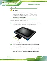
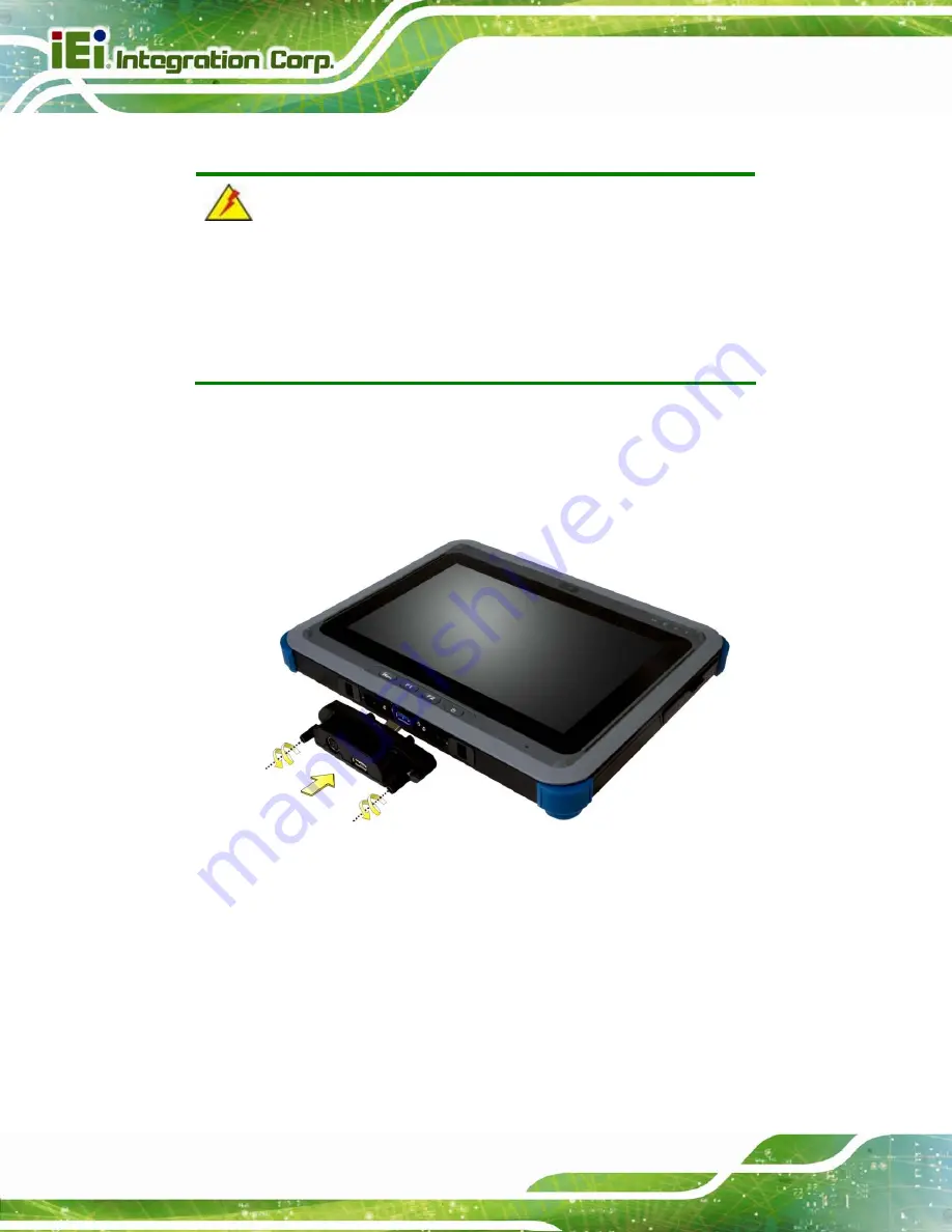
Install the charging adapter to the ICEROCK3-T10. Secure the charging adapter 

by tightening the two retention screws on either side of the adapter.   


Figure 3-1: Install Charging Adapter 

Step 2: 

Connect the ICEROCK3-T10 with a power source through the power adapter 

came with the package. 

Step 3: 

The system starts to charge the battery and the charge status LED lights up 

indicating the battery is being charged. When the battery is fully charged, the 

power status LED turns off. Please refer to 

Section 1.4.1: Status Indicators

Содержание ICEROCK3-T10

Страница 1: ...Page i User Manual Industrial Tablet PC Intel Core i7 CPU 8 GB DDR3 SDRAM USB 3 0 Micro HDMI microSD Slot 802 11b g n Wireless RFID Barcode Scanner Mobile 3 75G IP 65 RoHS Compliant Rev 1 01 May 20 2...

Страница 2: ...ion Date Version Changes May 20 2015 1 01 Added the following sections Section 3 10 Using 3 in 1 Combo Reader Section 4 10 SCR Driver Section 4 11 MSR Driver Section 4 12 Fingerprint Reader Driver Sep...

Страница 3: ...ossibility of such damages This document contains proprietary information protected by copyright All rights are reserved No part of this manual may be reproduced by any mechanical electronic or other...

Страница 4: ...0 2 UNPACKING 11 2 1 UNPACKING 12 2 2 PACKING LIST 13 3 INSTALLATION 15 3 1 CHARGE THE SYSTEM 16 3 1 1 Optional Charging Station 18 3 2 POWER UP THE SYSTEM 19 3 3 SD CARD INSTALLATION 20 3 4 SIM CARD...

Страница 5: ...4 11 MSR DRIVER OPTIONAL 54 4 12 FINGERPRINT READER DRIVER OPTIONAL 58 5 BIOS SETUP 60 5 1 INTRODUCTION 61 5 1 1 Starting Setup 61 5 1 2 Using Setup 61 5 1 3 Getting Help 62 5 1 4 BIOS Menu Bar 62 5...

Страница 6: ...ATTERY REPLACEMENT 92 A REGULATORY COMPLIANCE 94 B SAFETY PRECAUTIONS 99 B 1 SAFETY PRECAUTIONS 100 B 1 1 General Safety Precautions 100 B 1 2 Anti static Precautions 101 B 1 3 Product Disposal 102 B...

Страница 7: ...on Location 19 Figure 3 7 Install microSD Card 20 Figure 3 8 SIM Card Installation 21 Figure 3 9 PcscTool Location 22 Figure 3 10 NXP PCSC Tool Screen 22 Figure 3 11 NXP PCSC Tool Mode Selection 23 Fi...

Страница 8: ...tallShield Wizard 44 Figure 4 8 Bluetooth Driver Location 45 Figure 4 9 Bluetooth Driver InstallShield Wizard 46 Figure 4 10 RFID Driver Folder 47 Figure 4 11 RFID Driver Installation 47 Figure 4 12 U...

Страница 9: ...Figure 4 28 Driver Installation Complete Window 57 Figure 4 29 Device Manager Window 57 Figure 4 30 Fingerprint Reader Driver Folder 58 Figure 4 31 Fingerprint Reader Driver InstallShield Wizard 59 F...

Страница 10: ...ablet PC Page x List of Tables Table 1 1 Model Variations 3 Table 1 2 Status Indicators 5 Table 1 3 Technical Specifications 9 Table 2 1 Packing List 13 Table 2 2 Optional Items 14 Table 5 1 BIOS Navi...

Страница 11: ...art Technology 72 BIOS Menu 9 USB Configuration 73 BIOS Menu 10 iWDD Super IO Configuration 74 BIOS Menu 11 Serial Port 1 Configuration Menu 75 BIOS Menu 12 Hardware Health Configuration 77 BIOS Menu...

Страница 12: ......

Страница 13: ...ICEROCK3 T10 Tablet PC Page 1 Chapter 1 1 Introduction...

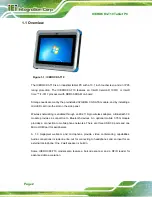
Страница 14: ...Wireless networking is enabled through an 802 11b g n wireless adapter A Bluetooth 3 0 module provides a connection to Bluetooth devices An optional mobile 3 75G module provides a connection to mobile...

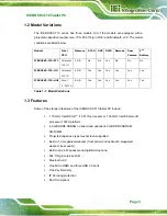
Страница 15: ...K3 T10 HUI Core i7 3517U 8 GB Yes Yes Yes Yes Yes Yes Table 1 1 Model Variations 1 3 Features Some of the standard features of the ICEROCK3 T10 tablet PC include 1 70 GHz Intel Core i7 3517U processor...

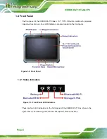
Страница 16: ...ted capacitive touchscreen Four LED indicators are also located on the front panel Figure 1 2 Front Panel 1 4 1 Status Indicators Figure 1 3 Front Panel LED Indicators There are four LED indicators on...

Страница 17: ...der is off Solid red the barcode scanner is turned on Solid blue the RFID reader is enabled Solid purple the barcode scanner and the RFID reader are both enabled Storage 3 75G Off the system is off or...

Страница 18: ...lt in battery and VESA mounting holes The optional 5 megapixel camera is also located on the rear panel Figure 1 4 Rear Panel 1 6 Side Panels The right side panel has a barcode on off button The left...

Страница 19: ...The barcode scanner is located on the top panel shown in the following diagram Figure 1 6 Top Panel 1 8 Bottom Panel The bottom panel has a USB 3 0 connector for installing USB peripheral devices or t...

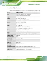
Страница 20: ...x Speaker 2 W 1 x Digital microphone on the front panel 1 x Analog microphone connector on the side panel Camera 1 x 1 3 megapixel webcam front panel 1 x Optional 5 megapixel webcam rear panel Displa...

Страница 21: ...75 mm x 75 mm Dimensions W x H x D 297 mm x 234 mm x 32 mm Operation Temperature 0 C 40 C Storage Temperature 20 C 60 C Humidity 5 95 non condensing Net Weight 1 9 kg IP Level IP 65 Safety CE FCC Dro...

Страница 22: ...ICEROCK3 T10 Tablet PC Page 10 1 10 Dimensions Figure 1 8 Dimensions units in mm...

Страница 23: ...ICEROCK3 T10 Tablet PC Page 11 Chapter 2 2 Unpacking...

Страница 24: ...sing an anti static wristband or similar device The installation steps below should be followed in order Step 1 Unpack the tablet PC Step 2 Check all the required parts are included Step 3 Charge the...

Страница 25: ...3 Make sure all the components listed in the packing list are present S t e p 0 2 2 Packing List The ICEROCK3 T10 tablet PC is shipped with the following components Quantity Item Image 1 ICEROCK3 T10...

Страница 26: ...ablet PC Page 14 These optional items are also available Item Image 3 in 1 combo reader P N ICEROCK3 3IN1 R10 Charging station P N ICEROCK3 CR01 R10 Carrying case P N 7Z000 ICEROCK3 10POUCH Table 2 2...

Страница 27: ...ICEROCK3 T10 Tablet PC Page 15 Chapter 3 3 Installation...

Страница 28: ...he steps below Step 1 Install the charging adapter to the ICEROCK3 T10 Secure the charging adapter by tightening the two retention screws on either side of the adapter Figure 3 1 Install Charging Adap...

Страница 29: ...The battery 1 capacity can be viewed by pressing the button on the battery pack Figure 3 3 Figure 3 3 Battery Capacity Indicators Step 5 The user can also turn on the system to check the battery capac...

Страница 30: ...ll the battery without turning off the system 3 1 1 Optional Charging Station The ICEROCK3 T10 can be charged through the optional charging station To charge the system install the ICEROCK3 T10 into t...

Страница 31: ...e 19 Figure 3 5 Charge the System through Charging Station 3 2 Power up the System To power up the system push the power button on the top panel for few seconds until the power button lights up Figure...

Страница 32: ...his section covers the installation of a microSD card Step 1 Open the I O cover on the side panel Locate the microSD card slot Step 2 Install the microSD card in the slot indicated below Figure 3 7 In...

Страница 33: ...he I O cover S t e p 0 3 5 Using RFID Reader There is a RFID reader on the front panel To use the RFID reader follow the steps below Step 1 Check the RFID status indicator on the front panel to make s...

Страница 34: ...CEROCK3 T10 Tablet PC Page 22 Figure 3 9 PcscTool Location Step 4 The NXP PCSC Tool window appears 4Figure 3 10 Figure 3 10 NXP PCSC Tool Screen Step 5 Select Automatic from the Mode menu 4Figure 3 11...

Страница 35: ...ode Selection Step 6 Choose Select a Reader from the Reader menu 4Figure 3 12 Figure 3 12 NXP PCSC Tool Reader Selection Step 7 The Select the reader window prompts Select a RFID reader and click OK S...

Страница 36: ...d RFID card Figure 3 14 NXP PCSC Tool Read RFID Card Step 9 Use the RFID reader to read a RFID card The RFID reader is located on the front panel as shown in Figure 3 15 The card information will be s...

Страница 37: ...n the BIOS menu If the barcode scanner is disabled please go to Chipset PCH IO Configuration BIOS menu to enable it refer to Section 5 4 1 Step 2 Install EZConfig Scanning barcode scanner program from...

Страница 38: ...blet PC Page 26 Figure 3 17 EZConfig Scanning InstallShield Wizard Step 4 Double click the EZConfig Scanning icon on the desktop The EZConfig Scanning window appears 4Figure 3 18 Figure 3 18 EZConfig...

Страница 39: ...for the barcode scanner After the configuration click the Config Comm button 4Figure 3 19 Port Number COM2 Baud Rate 115200 Parity Bits None Date Bits 8 Stop Bits 1 Hand Shaking 0 None Figure 3 19 EZC...

Страница 40: ...he RFID reader is enabled at the same time the indicator will turns from blue to purple Figure 3 20 Barcode On Off Button and Barcode Status Indicator Step 8 Scan a barcode and the barcode number will...

Страница 41: ...abled by default in the BIOS menu If the GPS function is disabled please go to Chipset PCH IO Configuration BIOS menu to enable it refer to Section 5 4 1 Step 2 Install the u center GPS evaluation sof...

Страница 42: ...aluation software Step 4 After the installation is complete double click the u center icon on the desktop The u center window appears 4Figure 3 23 Before start using the software please make sure the...

Страница 43: ...cs Standards Association compliant and can be mounted on a mounting device with a 75 mm interface pad The VESA mounting screw holes are located on the rear panel as shown in the following diagram To m...

Страница 44: ...ereo sound setup To install the audio devices follow the steps below Step 1 Identify the audio plugs The plugs on your headphone or speakers may not match the colors on the side panel audio jacks If a...

Страница 45: ...ht Step 0 3 9 2 Micro HDMI Device Connection There is one Micro HDMI connector on the left side of the ICEROCK3 T10 To connect a HDMI device please follow the instructions below Step 1 Located the Mic...

Страница 46: ...the ICEROCK3 T10 Step 0 3 9 3 USB Device Connection There are two USB 3 0 connectors on the side panel To connect a USB device please follow the instructions below Step 1 Located the USB connectors Th...

Страница 47: ...he USB device connector into the connector on the ICEROCK3 T10 Step 0 3 10 Using 3 in 1 Combo Reader Optional The 3 in 1 combo reader is an optional item for the ICEROCK3 T10 The combo reader combines...

Страница 48: ...o USB 3 0 connectors on the left side panel of the ICEROCK3 T10 Step 2 Insert and connect the USB connectors to install the combo reader See Figure 3 30 Figure 3 30 Combo Reader Installation Step 3 Se...

Страница 49: ...10 Tablet PC Page 37 Step 4 Install the drivers for these three reader by following the instructions described in Chapter 4 Section 4 10 SCR Driver Section 4 11 MSR Driver Section 4 12 Fingerprint Rea...

Страница 50: ...ICEROCK3 T10 Tablet PC Page 38 Chapter 4 4 Driver Installation...

Страница 51: ...river Bluetooth driver RFID driver USB 3 0 driver Wireless LAN driver Connect the Utility CD came with the ICEROCK3 T10 to the system and follow the installation instructions given below to install th...

Страница 52: ...rs to be installed Double click the setup file in each folder and follow the step by step instruction of the installation wizard to install the drivers 4 3 Intel Graphics Driver To install the graphic...

Страница 53: ...p 2 Double click the setup file in the folder The Intel Graphics Driver InstallShield Wizard appears 474Figure 4 3 Figure 4 3 Intel Graphics Driver InstallShield Wizard Step 3 Follow the step by step...

Страница 54: ...ease follow the steps below Step 1 Select GOBI 3000 from the list of the driver CD Locate the driver setup file in the Drivers folder as shown in 474Figure 4 6 Figure 4 4 3 75G Driver Location Step 2...

Страница 55: ...step by step instruction of the installation wizard to install the HD Audio driver 4 5 Audio Driver To install the driver for the speaker and the microphone please follow the steps below Step 1 Selec...

Страница 56: ...er Location Step 2 Double click the setup file in the folder The InstallShield Wizard screen appears 4Figure 4 7 Figure 4 7 Realtek HD Audio Driver InstallShield Wizard Step 3 Follow the step by step...

Страница 57: ...ver please follow the steps below Step 1 Select Wireless LAN Bluetooth from the list of the driver CD Select the Bluetooth folder as shown in 4Figure 4 8 Figure 4 8 Bluetooth Driver Location Step 2 Do...

Страница 58: ...ep by step instruction of the installation wizard to install the Bluetooth driver 4 7 RFID Driver To install the RFID driver please follow the steps below Step 1 Select RFID from the list of the drive...

Страница 59: ...OCK3 T10 Tablet PC Page 47 Figure 4 10 RFID Driver Folder Step 2 Follow the step by step instruction of the installation wizard Figure 4 11 to install the RFID driver Figure 4 11 RFID Driver Installat...

Страница 60: ...included in the Chipset driver folder see Section 4 2 and the other is in the USB 3 0 driver folder Please follow the instructions in these two sections to install the USB 3 0 drivers Step 1 Select US...

Страница 61: ...e step by step instruction of the installation wizard to install the graphics driver 4 9 Wireless LAN Driver To install the wireless LAN driver please follow the steps below Step 1 Select Wireless LAN...

Страница 62: ...tion Step 2 Double click the setup file in the Install_CD folder The InstallShield Wizard screen appears Figure 4 15 Figure 4 15 Wireless LAN InstallShield Wizard Step 3 Follow the step by step instru...

Страница 63: ...sys file at SCR DRIVER Windows Driver Singular See Figure 4 16 Copy the usbser sys file to C WINDOWS system32 drivers directory Figure 4 16 SCR Driver Folder usbser sys Step 2 Open the Device Manager...

Страница 64: ...e my computer for driver software Figure 4 18 Update Driver Software Window Step 4 The following window appears Press Click the Browse button to specify the SCR driver directory SCR DRIVER Windows Dri...

Страница 65: ...dow Figure 4 20 appears as the driver is installed Figure 4 20 Installing Driver Window Step 6 After the driver installation process is complete a confirmation screen appears Click Close to exit the p...

Страница 66: ...evice Manager Window 4 11 MSR Driver Optional Follow the steps below to install the MSR driver Step 1 Open the MSR driver folder and locate the usbser sys file at MSR Windows Driver Singular See Figur...

Страница 67: ...or right click Singular VCOM Card Reader Select Update Driver Software from the pop up window Figure 4 24 Device Manager Update Driver Software Step 3 The Update Driver Software window appears Select...

Страница 68: ...ck the Browse button to specify the MSR driver directory MSR Windows Driver Singular Then press click the Next button Figure 4 26 Browse for Driver Software Window Step 5 The following window Figure 4...

Страница 69: ...iver installation process is complete a confirmation screen appears Click Close to exit the program Figure 4 28 Driver Installation Complete Window Step 7 The Device Manager Window now shows the insta...

Страница 70: ...to install the fingerprint reader driver Step 1 The fingerprint reader driver is located in the folder shown in Figure 4 30 Double click the setup exe file in this folder to install the driver Figure...

Страница 71: ...ICEROCK3 T10 Tablet PC Page 59 Figure 4 31 Fingerprint Reader Driver InstallShield Wizard Step 3 Follow the step by step instruction of the installation wizard to install the fingerprint reader driver...

Страница 72: ...ICEROCK3 T10 Tablet PC Page 60 Chapter 5 5 BIOS Setup...

Страница 73: ...ress the ENTER key as soon as the system is turned on or 2 Press the ENTER key when the Press Enter to enter SETUP message appears on the screen 0 If the message disappears before the ENTER key is pre...

Страница 74: ...Getting Help When F1 is pressed a small help window describing the appropriate keys to use and the possible selections for the highlighted item appears To exit the Help Window press ESC or the F1 key...

Страница 75: ...ocessor ID 306a9 Stepping E1 Number of Processors 2Core s 4Thred s Microcode Revision 13 GT Info GT2 1000 MHz IGFX VBIOS Version 2143 Memory RC Version 1 7 0 0 Total Memory 8192 MB DDR3 Memory Frequen...

Страница 76: ...Time xx xx xx Use the System Time option to set the system time Manually enter the hours minutes and seconds 5 3 Advanced Use the Advanced menu 584BIOS Menu 2 to configure the CPU and peripheral devi...

Страница 77: ...F4 Save ESC Exit Version 2 15 1229 Copyright C 2012 American Megatrends Inc BIOS Menu 2 Advanced 5 3 1 ACPI Settings The ACPI Settings menu 84BIOS Menu 3 configures the Advanced Configuration and Pow...

Страница 78: ...red off Power to the RAM is maintained The computer returns slower to a working state but more power is saved 5 3 2 RTC Wake Settings The RTC Wake Settings menu 4BIOS Menu 4 configures RTC wake event...

Страница 79: ...be roused from a suspended state Disabled DEFAULT The real time clock RTC cannot generate a wake event Enabled If selected the following appears with values that can be selected Wake up every day Wake...

Страница 80: ...evice Found Enables or Disables BIOS support for security device O S will not show Security Device TCG EFI protocol and INT1A interface will not be available Select Screen Select Item Enter F1 General...

Страница 81: ...OS optimized for Hyper Threading Technology and Disabled for other OS OS not optimized for Hyper Threading Technology When Disabled only thread per enabled core is enabled Select Screen Select Item En...

Страница 82: ...the L3 cache Hyper Threading Enabled Use the Hyper Threading to enable or disable the CPU hyper threading function Disabled Disables the use of hyper threading technology Enabled DEFAULT Enables the u...

Страница 83: ...een Select Item EnterSelect F1 General Help F2 Previous Values F3 Optimized Defaults F4 Save ESC Exit Version 2 15 1229 Copyright C 2012 American Megatrends Inc BIOS Menu 7 SATA Configuration SATA Con...

Страница 84: ...Aptio Setup Utility Copyright C 2012 American Megatrends Inc Advanced Intel R Rapid Start Technology Disabled Select Screen Select Item EnterSelect F1 General Help F2 Previous Values F3 Optimized Defa...

Страница 85: ...m Enter F1 General Help F2 Previous Values F3 Optimized Defaults F4 Save ESC Exit Version 2 15 1229 Copyright C 2012 American Megatrends Inc BIOS Menu 9 USB Configuration USB Devices The USB Devices E...

Страница 86: ...or the serial ports Aptio Setup Utility Copyright C 2012 American Megatrends Inc Advanced iWDD Serial Ports Configuration Super IO Chip iWDD Serial Port 1 Configuration Serial Port 2 Configuration Ser...

Страница 87: ...ues F3 Optimized Defaults F4 Save ESC Exit Version 2 15 1229 Copyright C 2012 American Megatrends Inc BIOS Menu 11 Serial Port 1 Configuration Menu 5 3 8 1 1 Serial Port 1 Configuration Use the Serial...

Страница 88: ...4 5 3 8 1 2 Serial Port 2 Configuration Serial Port Enabled Use the Serial Port option to enable or disable the serial port Disabled Disable the serial port Enabled DEFAULT Enable the serial port Cha...

Страница 89: ...ws the operating temperature Aptio Setup Utility Copyright C 2012 American Megatrends Inc Advanced H W Monitor CPU Temperature 47 C Select Screen Select Item Enter F1 General Help F2 Previous Values F...

Страница 90: ...n when OS crashes Please install Auto Recovery API service before enabling this function Select Screen Select Item Enter F1 General Help F2 Previous Values F3 Optimized Defaults F4 Save ESC Exit Versi...

Страница 91: ...hipset BIOS menu may cause the system to malfunction Aptio Setup Utility Copyright C 2012 American Megatrends Inc Main Advanced Chipset Boot Security Save Exit PCH IO Configuration System Agent SA Con...

Страница 92: ...de Function Disabled Control Detection of the Azalia device Disabled Azalia will be unconditionally disabled Enabled Azalia will be unconditionally Enabled Select Screen Select Item Enter F1 General H...

Страница 93: ...Disabled Front camera function disabled Enabled DEFAULT Front camera function enabled Barcode Function Disabled Use the Barcode Function option to enable or disable the barcode function Disabled DEFA...

Страница 94: ...tooth Function Enabled Use the Bluetooth Function option to enable or disable the Bluetooth function Disabled Bluetooth function disabled Enabled DEFAULT Bluetooth function enabled Windows Rotation Fu...

Страница 95: ...Graphics Configuration Memory Configuration Check to enable VT d function on MCH Select Screen Select Item Enter Select Change Opt F1 General Help F2 Previous Values F3 Optimized Defaults F4 Save Exi...

Страница 96: ...evice should be Primary Display Or select SG for Switchable Gfx Select Screen Select Item Enter Select Change Opt F1 General Help F2 Previous Values F3 Optimized Defaults F4 Save Exit ESC Exit Version...

Страница 97: ...f memory that can be allocated for the internal graphics device Configuration options are listed below 128M 256M MAX DEFAULT Primary IGFX Boot Display VBIOS Default Use the Primary IGFX Boot Display o...

Страница 98: ...1229 Copyright C 2012 American Megatrends Inc BIOS Menu 18 Memory Configuration 5 5 Boot Use the Boot menu 584BIOS Menu 19 to configure system boot options Aptio Setup Utility Copyright C 2012 America...

Страница 99: ...f Does not enable the keyboard Number Lock automatically To use the 10 keys on the keyboard press the Number Lock key located on the upper left hand corner of the 10 key pad The Number Lock LED on the...

Страница 100: ...C 2012 American Megatrends Inc Main Advanced Chipset Boot Security Save Exit Password Description If ONLY the Administrator s password is set then this only limits access to Setup and is only asked f...

Страница 101: ...s and Reset Discard Changes and Reset Restore Defaults Save as User Defaults Restore User Defaults Exit system setup after saving the changes Select Screen Select Item EnterSelect F1 General Help F2 P...

Страница 102: ...lues for each of the parameters on the Setup menus F3 key can be used for this operation Save as User Defaults Use the Save as User Defaults option to save the changes done so far as user defaults Res...

Страница 103: ...ICEROCK3 T10 Tablet PC Page 91 Chapter 6 6 System Maintenance...

Страница 104: ...Replacement In the case of motherboard failure please contact an IEI sales representative reseller or system vendor The motherboard is accessible after opening the rear cover 6 3 Battery Replacement T...

Страница 105: ...ICEROCK3 T10 Tablet PC Page 93 Figure 6 2 Battery Installation Step 4 Lock the battery by rotating the battery latches to a proper position...

Страница 106: ...ICEROCK3 T10 Tablet PC Page 94 Appendix A A Regulatory Compliance...

Страница 107: ...with the essential requirements and other relevant provisions of Directive 1999 5 EC Bulgarian IEI Integration Corp 1999 5 esky Czech IEI Integration Corp t mto prohla uje e tento za zen je ve shod s...

Страница 108: ...Lietuvi Lithuanian IEI Integration Corp deklaruoja kad is ranga atitinka esminius reikalavimus ir kitas 1999 5 EB Direktyvos nuostatas Nederlands Dutch IEI Integration Corp dat het toestel toestel in...

Страница 109: ...ili direktive 1999 5 ES Slovensky Slovak IEI Integration Corp t mto vyhlasuje e zariadenia sp a z kladn po iadavky a v etky pr slu n ustanovenia Smernice 1999 5 ES Suomi Finnish IEI Integration Corp...

Страница 110: ...Class A digital device pursuant to part 15 of the FCC Rules These limits are designed to provide reasonable protection against harmful interference when the equipment is operated in a commercial envi...

Страница 111: ...ICEROCK3 T10 Tablet PC Page 99 Appendix B B Safety Precautions...

Страница 112: ...g installed moved or modified Do not apply voltage levels that exceed the specified voltage range Doing so may cause fire and or an electrical shock Electric shocks can occur if the ICEROCK3 T10 chass...

Страница 113: ...following anti static precautions are strictly adhered to Wear an anti static wristband Wearing a simple anti static wristband can help to prevent ESD from damaging any electrical component Self groun...

Страница 114: ...al and electronic products carrying the mark left must be disposed of separately from normal household waste This includes monitors and electrical accessories such as signal cables or power cords When...

Страница 115: ...ng a product specifically designed for the purpose In such case the product will be explicitly mentioned in the cleaning tips Below is a list of items to use for cleaning Cloth Although paper towels o...

Страница 116: ...ICEROCK3 T10 Tablet PC Page 104 Appendix C C BIOS Options...

Страница 117: ...ed 73 Serial Port Enabled 75 Change Settings Auto 75 Serial Port Enabled 76 Change Settings Auto 76 PC Health Status 77 Auto Recovery Function Disabled 78 Azalia Enabled 80 Azalia Internal HDMI Codec...

Страница 118: ...t Boot Enabled 87 Option ROM Messages Force BIOS 87 UEFI Boot Disabled 88 Boot Option 1 SATA PM MRMAJ5A03 88 Hard Drive BBS Priorities 88 Administrator Password 89 User Password 89 Save Changes and Re...

Страница 119: ...ICEROCK3 T10 Tablet PC Page 107 Appendix D D Terminology...

Страница 120: ...a binary 0 while a high amplitude signal represents a binary 1 BIOS The Basic Input Output System BIOS is firmware that is first run when the computer is turned on and can be configured by the end use...

Страница 121: ...dStep Technology EIST allows users to modify the power consumption levels and processor performance through application software The application software changes the bus to core frequency ratio and th...

Страница 122: ...ransfers between storage devices and the computer chipsets The SATA bus has transfer speeds up to 1 5 Gbps and the SATA II bus has data transfer speeds of up to 3 0 Gbps S M A R T Self Monitoring Anal...

Страница 123: ...ICEROCK3 T10 Tablet PC Page 111 Appendix E E Watchdog Timer...

Страница 124: ...BIOS function call INT 15H is used to control the Watchdog Timer INT 15H AH 6FH Sub function AL 2 Sets the Watchdog Timer s period BL Time out value Its unit second is dependent on the item Watchdog T...

Страница 125: ...system resets Example program INITIAL TIMER PERIOD COUNTER W_LOOP MOV AX 6F02H setting the time out value MOV BL 30 time out value is 48 seconds INT 15H ADD THE APPLICATION PROGRAM HERE CMP EXIT_AP 1...

Страница 126: ...ICEROCK3 T10 Tablet PC Page 114 Appendix F F Hazardous Materials Disclosure...

Страница 127: ...presences of small quantities of certain materials in the product and is applicable to China RoHS only A label will be placed on each product to indicate the estimated Environmentally Friendly Use Pe...

Страница 128: ...t Board O O O O O O Metal Fasteners O O O O O O Cable Assembly O O O O O O Fan Assembly O O O O O O Power Supply Assemblies O O O O O O Battery O O O O O O O This toxic or hazardous substance is conta...

Страница 129: ...ICEROCK3 T10 Tablet PC Page 117 RoHS RoHS Pb Hg Cd CR VI PBB PBDE O O O O O O O O O O O O O O O O O O O O O O O O O O O O O O O O O O O O O O O O O O O O O O O O O SJ T11363 2006 X SJ T11363 2006...

Отзывы: