background image


ECW-281BB6 Embedded System


2E0  

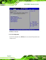
Serial port 5 I/O port address is 2E0 


2D8 


Serial port 5 I/O port address is 2D8 


2D0 


Serial port 5 I/O port address is 2D0 


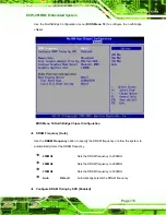
Serial Port5 IRQ [11] 

Use the 

Serial Port5 IRQ

 option to select the interrupt address for serial port 5. 


Serial port 4 IRQ address is 3 


Serial port 4 IRQ address is 9 


10  

Serial port 4 IRQ address is 10 


11 D

EFAULT


Serial port 4 IRQ address is 11 


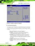
Serial Port6 Address [2E0] 

Use the 

Serial Port6 IRQ

 option to select the interrupt address for serial port6. 


Disabled


No base address is assigned to serial port 3 


3E8 


Serial port 6 I/O port address is 3E8 


2E8 


Serial port 6 I/O port address is 2E8 


2F0 


Serial port 6 I/O port address is 2F0 


2E0 D

EFAULT


Serial port 6 I/O port address is 2E0 


2D8 


Serial port 6 I/O port address is 2D8 


2D0 


Serial port 6 I/O port address is 2D0 


Serial Port6 IRQ [10] 

Use the 

Serial Port6 IRQ

 option to select the interrupt address for serial port 6. 


Page 98 

Содержание ECW-281BB6

Страница 1: ...ECW 281BB6 Embedded System Page 1 ECW 281BB6 Embedded System...

Страница 2: ...ECW 281BB6 Embedded System Revision ECW 281BB6 Embedded System Date Version Changes June 2007 1 00 Initial release Page 2...

Страница 3: ...ocumentation even if advised of the possibility of such damages This document contains proprietary information protected by copyright All rights are reserved No part of this manual may be reproduced b...

Страница 4: ...ales representative directly To contact an IEI sales representative please send an email to sales iei com tw The items listed below should all be included in the ECW 281BB6 package 1 x ECW 281BB6 embe...

Страница 5: ...may occur with installations in environments where flammable gases are present 7 Fault tolerant and failsafe designs should be implemented with the use of the embedded system on transportation vehicle...

Страница 6: ...difications made to the equipment that are not expressly approved by the relevant standards could void the authority to operate the equipment MAINTENANCE AND CLEANING Note the following precautions be...

Страница 7: ...cloth a bit with some water or rubbing alcohol and rub it on the computer Unknown solvents may be harmful to the plastics parts Vacuum cleaner Removing the dust dirt hair cigarette particles and other...

Страница 8: ...TION 27 2 1 ECW 281BB6 MECHANICAL OVERVIEW 28 2 2 PHYSICAL DIMENSIONS 28 2 2 1 ECW 281BB6 Dimensions 28 2 2 2 Motherboard Dimensions 29 2 2 3 Power Module Dimensions 30 2 3 EXTERNAL OVERVIEW 31 2 3 1...

Страница 9: ...50 3 4 1 External Peripheral Interface Connector Overview 50 3 4 2 RJ 45 Ethernet Connector 51 3 4 3 Serial Port Connector COM1 52 3 4 4 USB Combo Ports 53 3 4 5 VGA Connector 53 3 5 WAFER 8522 MOTHE...

Страница 10: ...able to Reboot After Configuration Changes 81 5 1 5 BIOS Menu Bar 81 5 2 MAIN 82 5 3 ADVANCED 83 5 3 1 CPU Configuration 84 5 3 2 IDE Configuration 86 5 3 2 1 IDE Master IDE Slave 89 5 3 3 Super IO Co...

Страница 11: ...NENT REPLACEMENT PROCEDURE 138 7 3 1 SO DIMM Replacement 139 A IEI EMBEDDED SYSTEM SERIES 143 A 1 IEI EMBEDDED SYSTEM SERIES 144 A 1 1 Overview 144 A 1 2 IEI Embedded System Series 144 A 1 3 IEI Embed...

Страница 12: ...System B 1 BIOS CONFIGURATION OPTIONS 152 C WATCHDOG TIMER 155 D ADDRESS MAPPING 159 D 1 IO ADDRESS MAP 160 D 2 1ST MB MEMORY ADDRESS MAP 161 D 3 IRQ MAPPING TABLE 161 D 4 DMA CHANNEL ASSIGNMENTS 161...

Страница 13: ...Location 41 Figure 3 4 Audio Connector Pinouts 42 Figure 3 5 IDE Device Connector Location 43 Figure 3 6 LED Connector Locations 45 Figure 3 7 Power Button Connector Location 46 Figure 3 8 Reset Butto...

Страница 14: ...14 Power Button 77 Figure 6 1 InstallShield Wizard Preparation Screen 124 Figure 6 2 Welcome Screen 125 Figure 6 3 License Agreement 125 Figure 6 4 Readme Information 126 Figure 6 5 Restart the Comput...

Страница 15: ...Select the Driver Directory 133 Figure 6 19 LAN Driver Configuration 134 Figure 7 1 SO DIMM Cover Plate 139 Figure 7 2 SO DIMM Removal 140 Figure 7 3 SO DIMM Thermal Bracket Retention Screws 140 Figur...

Страница 16: ...44 Table 3 8 LED Connector Pinouts 45 Table 3 9 Power Button Connector Pinouts 46 Table 3 10 Reset Button Connector Pinouts 47 Table 3 11 RS 232 422 485 Serial Port Connector Pinouts 48 Table 3 12 RS...

Страница 17: ...W 281BB6 Embedded System Table 3 25 Motherboard Power Connector Mapping 61 Table 3 26 Motherboard Power Connector Mapping 61 Table 4 1 Package List Contents 66 Table 5 1 BIOS Navigation Keys 81 Page 1...

Страница 18: ...on 99 Menu 8 MPS Configuration 100 Menu 9 Trusted Computing 101 Menu 10 USB Configuration 102 Menu 11 USB Mass Storage Device Configuration 104 Menu 12 Boot 106 BIOS Menu 13 Boot Settings Configuratio...

Страница 19: ...ECW 281BB6 Embedded System Chapter 1 1 Introduction Page 19...

Страница 20: ...trial computer ECW 281BB6 embedded subsystems are all capable of supporting one 2 5 hard disk drive 1 1 1 ECW 281BB6 Benefits The ECW 281BB6 embedded system has the following benefits Easy installatio...

Страница 21: ...9V 36V DC input The four models are listed in Table 1 1 below ECW 281BB6 CPU Memory Power 512MB Intel Celeron M 1GHz zero cache 512MB DDR 12V DC input 1GB Intel Celeron M 1GHz zero cache 1GB DDR 12V D...

Страница 22: ...uminum Alloy Power Supply Internal DC to DC power converter input voltage 12V DC or 9V 36V WD External power adapter input voltage 90V AC 264V AC 47Hz 63Hz 55W Operating Shock 1G 5Hz 500Hz random oper...

Страница 23: ...input support depends on the power module installed in the system The two power modules are listed in Table 1 3 Embedded System Power Module DC Input ECW 281BB6 512MB IDD 12250A 12V DC input ECW 281BB...

Страница 24: ...tput 12V 5A pass thru 3A Max 5V 10A Max 10A Max 5VSB 0 5A Max 0 5A Max Max Total Output 50W 60W 12V pass thru 60W Performance Characteristics Noise Ripple 240mV 240mV Line Regulation 20mV 20mV Load Re...

Страница 25: ...Adapter The specifications for the adapter are listed in Table 1 5 Nominal 12 0V Regulation 11 52V 12 48V Ripple Noise 120mV Min 0A Output Max 4 58A Short Circuit Output can be shorted without damage...

Страница 26: ...sing 0 95 Relative Humidity Storage non condensing 0 95 Operating 1G 5Hz 500Hz random vibration 30mins axis 3 direction Vibration Storage 2G 5Hz 500Hz random vibration 30mins axis 3 direction Operatin...

Страница 27: ...ECW 281BB6 Embedded System Chapter 2 2 Mechanical Description Page 27...

Страница 28: ...pplications that require low power consumption Featuring two LAN four USB six serial communication ports as well as audio and VGA the ECW 281BB6 offers system integrators and developers the best selec...

Страница 29: ...ECW 281BB6 Embedded System Figure 2 1 ECW 281BB6 Dimensions mm 2 2 2 Motherboard Dimensions The WAFER series dimension are listed below and shown in Figure 2 2 Length 145 00mm Width 102 00mm Page 29...

Страница 30: ...d System Figure 2 2 WAFER SBC Dimensions mm 2 2 3 Power Module Dimensions The power module dimensions are listed below and shown in Figure 2 3 Length 100 00mm Width 40 00mm Figure 2 3 Power Module Dim...

Страница 31: ...he front panel is shown in Figure 2 4 below Figure 2 4 ECW 281BB6 Front Panel 2 3 2 Rear Panel The rear panel of the ECW 281BB6 provides access to the following external I O connectors 2 x USB port co...

Страница 32: ...om access panel from the chassis while power is still being fed into the system Before removing the bottom access panel make sure the system has been turned off and all power connectors unplugged The...

Страница 33: ...281BB6 internal components are listed below 1 x IEI WAFER motherboard preinstalled 1 x IEI power module preinstalled 1 x SO DIMM module preinstalled 1 x Hard drive bracket and IDE cable support one ID...

Страница 34: ...ECW 281BB6 Embedded System Page 34 Figure 2 7 Internal Overview...

Страница 35: ...ECW 281BB6 Embedded System Chapter 3 3 System Components Page 35...

Страница 36: ...or a complete list of jumpers and connectors on the WAFER 8522 motherboard please refer to the WAFER 8522 user manual The ECW 281BB6 models have a WAFER 8522 motherboard installed in the system The fo...

Страница 37: ...Celeron M processor is installed on the WAFER 8522 motherboard Specifications for the processors are listed in Table 3 1 below Family Architecture Cache Clock Speed FSB ULV Intel Celeron M 90 nm 512...

Страница 38: ...ector 3 pin wafer connector CN8 Audio connector 10 pin box header CN4 IDE Interface connector 44 pin box header IDE1 LED connector 6 pin header CN3 Power button connector 2 pin wafer connector CN7 Res...

Страница 39: ...Peripheral Connectors Internal peripheral connectors are found on the motherboard and are only accessible when the motherboard is outside of the chassis This section has complete descriptions of all t...

Страница 40: ...SCRIPTION 1 12V 2 GROUND 3 GROUND 4 5V Table 3 4 AT Power Connector Pinouts 3 3 2 ATX Power Connector CN Label CN8 CN Type 3 pin wafer connector 1x3 CN Location See Figure 3 3 CN Pinouts See Table 3 5...

Страница 41: ...1 5V_SB 2 GROUND 3 PS_ON Table 3 5 ATX Power Connector Pinouts 3 3 3 Audio Connector CN Label CN4 CN Type 10 pin box header 2x5 CN Location See Figure 3 4 CN Pinouts See Table 3 6 The 10 pin audio co...

Страница 42: ...UND 4 GROUND 5 LINEOUT_L 6 LINEIN_L 7 GROUND 8 GROUND 9 MIC1IN 10 MIC2IN Table 3 6 Audio Connector Pinouts 3 3 4 IDE Connector CN Label IDE1 CN Type 44 pin box header 2x22 CN Location See Figure 3 5 C...

Страница 43: ...3 5 IDE Device Connector Location PIN NO DESCRIPTION PIN NO DESCRIPTION 1 RESET 2 GROUND 3 DATA 7 4 DATA 8 5 DATA 6 6 DATA 9 7 DATA 5 8 DATA 10 9 DATA 4 10 DATA 11 11 DATA 3 12 DATA 12 13 DATA 2 14 DA...

Страница 44: ...SA2 37 HDC CS0 38 HDC CS1 39 HDD ACTIVE 40 GROUND 41 5V 42 5V 43 GROUND 44 N C Table 3 7 IDE Connector Pinouts 3 3 5 LED Connector CN Label CN3 CN Type 6 pin header 1x6 CN Location See Figure 3 6 CN...

Страница 45: ...5 HDLED 6 HDLED Table 3 8 LED Connector Pinouts 3 3 6 Power Button Connector CN Label CN7 CN Type 2 pin wafer connector 1x2 CN Location See Figure 3 7 CN Pinouts See Table 3 9 The power button connect...

Страница 46: ...or Pinouts 3 3 7 Reset Button Connector CN Label CN6 CN Type 2 pin wafer connector 1x2 CN Location See Figure 3 8 CN Pinouts See Table 3 10 The reset button connector is connected to a reset switch on...

Страница 47: ...N Type 14 pin header 2x7 CN Location See Figure 3 9 CN Pinouts See Table 3 11 The serial port connectors connect to RS 232 RS 422 or RS 485 serial port device Figure 3 9 Serial Port Connector Location...

Страница 48: ...le 3 12 The 40 pin serial port connector contains the following four serial ports COM 3 COM 4 COM 5 and COM 6 All four serial ports are RS 232 serial communications channels The serial port locations...

Страница 49: ...17 DTR_COM4 18 RI_COM4 19 GND 20 GND 21 DCD_COM5 22 DSR_COM5 23 RXD_COM5 24 RTS_COM5 25 TXD_COM5 26 CTS_COM5 27 DTR_COM5 28 RI_COM5 29 GND 30 GND 31 DCD_COM6 32 DSR_COM6 33 RXD_COM6 34 RTS_COM6 35 TX...

Страница 50: ...RIPTION 1 VCC 2 GROUND 3 DATA0 4 DATA0 5 DATA0 6 DATA0 7 GROUND 8 VCC Table 3 13 Internal USB Connector Pinouts 3 4 External Peripheral Interface Connectors 3 4 1 External Peripheral Interface Connect...

Страница 51: ...Figure 3 12 CN Pinouts See Table 3 14 The RJ 45 Ethernet connector on the WAFER 8522 provides connectivity to a GbE Ethernet connection between the WAFER 8522 and a Local Area Network LAN through a ne...

Страница 52: ...RANGE 100Mbps connection YELLOW Linked GREEN 1Gbps connection BLINKING Data Activity Table 3 15 RJ 45 Ethernet Connector LEDs 3 4 3 Serial Port Connector COM1 CN Label COM1 CN Type DB 9 connector CN L...

Страница 53: ...17 The two USB combo ports provide connectivity to USB devices The USB port support both USB 1 1 and USB 2 0 PIN NO DESCRIPTION PIN NO DESCRIPTION 1 USBVCC0 5 USBVCC1 2 USBP0 6 USBP1 3 USBP0 7 USBP1 4...

Страница 54: ...nnector connects to a CRT or LCD monitor directly PIN DESCRIPTION PIN DESCRIPTION 1 RED 9 5V 2 GREEN 10 GROUND 3 BLUE 11 NC 4 NC 12 DDCDAT 5 GROUND 13 HSYNC 6 5V 14 VSYNC 7 GROUND 15 DDCCLK 8 GROUND T...

Страница 55: ...the pins of the jumper with the plastic clip and to OPEN a jumper means removing the plastic clip from a jumper Figure 3 16 Jumpers The WAFER 8522 motherboard has several onboard jumpers Table 3 19 De...

Страница 56: ...t up process the fault may be corrected by pressing the F1 to enter the CMOS Setup menu Do one of the following Enter the correct CMOS setting Load Optimal Defaults Load Failsafe Defaults After having...

Страница 57: ...gure 3 18 The JP4 jumper sets the communication protocol used by the second serial communications port COM 2 as RS 232 RS 422 or RS 485 The COM Port Setting jumper selection options are shown in Table...

Страница 58: ...guide that came with the monitor to select the correct voltage Jumper Label JP5 Jumper Type 3 pin header Jumper Settings See Table 3 22 Jumper Location See Figure 3 19 The LCD Voltage Selection jumpe...

Страница 59: ...ution jumper to select the resolution of the LCD The LCD Resolution settings are shown in Table 3 23 PIN NO 7 8 5 6 3 4 1 2 Description Open Open Open Open For BIOS Setting Open Open Open Short Type 0...

Страница 60: ...t Short Short Open Type 13 Reserved Short Short Short Short Type 14 Reserved Table 3 23 LCD Resolution Jumper Settings The LCD resolution jumper location is shown in Figure 3 20 Figure 3 20 LCD Resolu...

Страница 61: ...odule CN5 Power CN4 Output Power Pin 1 Pin 4 Pin 2 Pin 3 Pin 3 Pin 2 Pin 4 Pin 1 Table 3 24 Motherboard Power Connector Mapping 3 6 2 ATX Mode Connector The connector mapping for the ATX mode connecto...

Страница 62: ...ECW 281BB6 Embedded System THIS PAGE IS INTENTIONALLY LEFT BLANK Page 62...

Страница 63: ...ECW 281BB6 Embedded System Chapter 4 4 Installation Page 63...

Страница 64: ...ed to Wear an anti static wristband Wearing a simple anti static wristband can help to prevent ESD from damaging the board Self grounding Before handling the board touch any grounded conducting materi...

Страница 65: ...s are included in the package If any of these components are missing please contact the ECW 281BB6 reseller or vendor where it was purchased or contact an IEI sales representative immediately Quantity...

Страница 66: ...ECW 281BB6 Embedded System 1 Mini jumper pack 1 Quick installation guide 1 Driver and manual CD 1 Power Adaptor for WD models only 1 Wall mount kit optional Table 4 1 Package List Contents Page 66...

Страница 67: ...hassis with six retention screws Figure 4 1 All six screws must be removed Figure 4 1 Bottom Surface Retention Screws Step 2 Gently remove the bottom surface from the ECW 281BB6 Step 0 4 2 4 Configure...

Страница 68: ...ttom panel Figure 4 2 Figure 4 2 Hard Drive Bracket To install the hard drive into the system please follow the steps below Step 1 Remove the bottom surface See Section 4 2 3 Step 2 Remove the hard dr...

Страница 69: ...s into the bottom of the bracket Figure 4 4 Figure 4 4 HDD Retention Screws Step 6 Locate the breather hole of the HDD Cut off the corresponding area of the breather hole from the thermal pad Step 7 A...

Страница 70: ...ce the bottom surface to the bottom panel by reinserting the six previously removed retention screws Step 0 4 2 6 Mounting the System with Mounting Brackets To mount the embedded system onto a wall or...

Страница 71: ...nt Kit To mount the embedded system onto a wall using the VESA MIS D 100 wall mount kit please follow the steps below Step 1 Select the location on the wall for the wall mounting bracket Step 2 Carefu...

Страница 72: ...bottom panel Figure 4 8 Step 1 Align the mounting screws on the ECW 281BB6 bottom panel with the mounting holes on the bracket Step 2 Carefully insert the screws through the holes and gently pull the...

Страница 73: ...unting To mount the ECW 281BB6 embedded system onto a DIN rail please follow the steps below Step 3 Attach the DIN rail mounting bracket to the bottom panel of the embedded system Secure the bracket t...

Страница 74: ...ed screw in the center of the bracket is at the lowest position of the elongated hole Figure 4 10 Figure 4 10 Screw Locations Step 5 Place the DIN rail flush against the back of the mounting bracket m...

Страница 75: ...wise This draws the lower clamp up and secures the embedded system to the DIN rail Figure 4 12 Step 0 Figure 4 12 Secure the Assembly to the DIN Rail 4 2 9 Cable Connections Once the system has been m...

Страница 76: ...applied to the system may cause damage to the internal electronic components and may also cause injury to the user To power on the embedded system please make sure of the following The bottom surface...

Страница 77: ...is connected to the ground pin on the input power connector of the power module 4 3 3 Power on Procedure To power on the ECW 281BB6 please follow the steps below Step 1 Push the power button Step 2 On...

Страница 78: ...ECW 281BB6 Embedded System THIS PAGE IS INTENTIONALLY LEFT BLANK Page 78...

Страница 79: ...ECW 281BB6 Embedded System Chapter 5 5 BIOS Settings Page 79...

Страница 80: ...essage appears on the screen 0 If the message disappears before the DELETE key is pressed restart the computer and try again 5 1 2 Using Setup Use the arrow keys to highlight items press ENTER to sele...

Страница 81: ...not boot after changes to the system configuration is made CMOS defaults Use the jumper described in Chapter Error Reference source not found Section 3 5 1 5 1 5 BIOS Menu Bar The menu bar on top of t...

Страница 82: ...a brief summary of different system components The fields in System Overview cannot be changed The items shown in the system overview include AMI BIOS Displays auto detected BIOS information o Version...

Страница 83: ...tem date Manually enter the day month and year 5 3 Advanced Use the Advanced menu BIOS Menu 2 to configure the CPU and peripheral devices through the following sub menus WARNING Setting the wrong valu...

Страница 84: ...ECW 281BB6 Embedded System BIOS Menu 2 Advanced 5 3 1 CPU Configuration Use the CPU Configuration menu BIOS Menu 3 to view detailed CPU specifications and configure the CPU Page 84...

Страница 85: ...s the name of the CPU manufacturer Brand String Lists the brand name of the CPU being used Frequency Lists the CPU processing speed FSB Speed Lists the FSB speed Cache L1 Lists the CPU L1 cache size C...

Страница 86: ...acks Disabled Code can be executed in any memory area Enabled DEFAULT Code execution in data only memory pages is prohibited 5 3 2 IDE Configuration Use the IDE Configuration menu BIOS Menu 4 to chang...

Страница 87: ...and Secondary Slave Both DEFAULT Allows the system to detect both the Primary and Secondary IDE channels including the Primary Master Primary Slave Secondary Master and Secondary Slave Onboard PCI IDE...

Страница 88: ...s 0 seconds and a large majority of ultra ATA hard disk drives can be detected well within 35 seconds the default setting ATA PI 80Pin Cable Detection Host Device When an Ultra ATA 66 an Ultra ATA 100...

Страница 89: ...the IDE Configuration menu Primary IDE Master Primary IDE Slave Secondary IDE Master Secondary IDE Slave The IDE Configuration menu BIOS Menu 4 allows changes to the configurations for the IDE devices...

Страница 90: ...g hard disk CD ROM etc LBA Mode Indicates whether the LBA Logical Block Addressing is a method of addressing data on a disk drive is supported or not Block Mode Block mode boosts IDE drive performanc...

Страница 91: ...ng should be used if an IDE hard disk drive is attached to the specified channel CD DVD The CD DVD option specifies that an IDE CD ROM drive is attached to the specified IDE channel The BIOS does not...

Страница 92: ...ive on the specified channel If supported the data transfer to and from the device occurs multiple sectors at a time PIO Mode Auto Use the PIO Mode option to select the IDE PIO Programmable I O mode p...

Страница 93: ...to auto detect disable or enable Self Monitoring Analysis and Reporting Technology SMART on the drive on the specified channel S M A R T predicts impending drive failures The S M A R T BIOS option ena...

Страница 94: ...rt1 Address 3F8 IRQ4 Use the Serial Port1 Address option to select the Serial Port 1 base address Disabled No base address is assigned to Serial Port 1 3F8 IRQ4 DEFAULT Serial Port 1 I O port address...

Страница 95: ...address Disabled No base address is assigned to Serial Port 2 2F8 IRQ3 DEFAULT Serial Port 2 I O port address is 3F8 and the interrupt address is IRQ3 3E8 IRQ4 Serial Port 2 I O port address is 3E8 an...

Страница 96: ...select the base addresses for serial port 3 Disabled No base address is assigned to serial port 3 3E8 DEFAULT Serial port 3 I O port address is 3E8 2F8 Serial port 3 I O port address is 2F8 3E8 Seria...

Страница 97: ...is 2F0 2E0 Serial port 4 I O port address is 2E0 Serial Port4 IRQ 10 Use the Serial Port4 IRQ option to select the interrupt address for serial port 4 3 Serial port 4 IRQ address is 3 9 Serial port 4...

Страница 98: ...LT Serial port 4 IRQ address is 11 Serial Port6 Address 2E0 Use the Serial Port6 IRQ option to select the interrupt address for serial port6 Disabled No base address is assigned to serial port 3 3E8 S...

Страница 99: ...0 11 Serial port 6 IRQ address is 11 5 3 4 Hardware Health Configuration The Hardware Health Configuration menu BIOS Menu 7 shows the operating temperature fan speeds and system voltages BIOS Menu 7 H...

Страница 100: ...emperature Sensor 1 o Temperature Sensor 2 Voltages The following system voltages are monitored o CPU Core o VCC o 3 3V o 5 0V o 1 5V o VBAT 5 3 5 MPS Configuration Use the MPS Configuration menu BIOS...

Страница 101: ...sed 1 1 DEFAULT MPS version 1 1 is used 1 4 MPS version 1 4 is used 5 3 6 Trusted Computing Use the Trusted Computing menu BIOS Menu 9 to configure TPM parameters BIOS Menu 9 Trusted Computing TPM Dev...

Страница 102: ...nfiguration Use the USB Configuration menu BIOS Menu 10 to read USB configuration information and configure the USB settings BIOS Menu 10 USB Configuration USB Configuration The USB Configuration fiel...

Страница 103: ...is not enabled any attached USB mouse or USB keyboard does not become available until a USB compatible operating system is fully booted with all USB drivers loaded When this option is enabled any atta...

Страница 104: ...s HiSpeed The controller is capable of operating at 480Mb s 5 3 7 1 USB Mass Storage Device Configuration Use the USB Mass Storage Device Configuration menu BIOS Menu 11 to configure USB mass storage...

Страница 105: ...DOS Microsoft Windows 95 and Microsoft Windows 98 can be used for this purpose Auto DEFAULT BIOS auto detects the current USB Floppy The USB device will be emulated as a floppy drive The device can b...

Страница 106: ...n 5 4 Boot Use the Boot menu BIOS Menu 12 to configure system boot options BIOS Menu 12 Boot 5 4 1 Boot Settings Configuration Use the Boot Settings Configuration menu BIOS Menu 13 to configure advanc...

Страница 107: ...he boot process Disabled No POST procedures are skipped Enabled DEFAULT Some POST procedures are skipped to decrease the system boot time Quiet Boot Disabled Use the Quiet Boot BIOS option to select t...

Страница 108: ...the system clock generator pulses have extreme values Spreading the pulse spectrum modulates changes in the extreme values from spikes to flat curves thus reducing the EMI This benefit may in some cas...

Страница 109: ...s menu BIOS Menu 15 to specify the boot sequence of the available drives When the menu is opened the removable drives connected to the system are listed as shown below 1st Drive 1st USB NOTE Only the...

Страница 110: ...Drive option is selected a list of available drives is shown Select the first drive the system boots from If the 1st Drive is not used for booting this option may be disabled BIOS Menu 15 Removable Dr...

Страница 111: ...elect this field and enter the password After the password has been added Install appears next to Change Supervisor Password Change User Password Use the Change User Password to set or change a user p...

Страница 112: ...set Use the Chipset menu BIOS Menu 17 to access the NorthBridge and SouthBridge configuration menus WARNING Setting the wrong values for the Chipset BIOS selections in the Chipset BIOS menu may cause...

Страница 113: ...RAM Frequency Auto Use the DRAM Frequency option to specify the DRAM frequency or allow the system to automatically detect the DRAM frequency 200MHz Sets the DRAM frequency to 200MHz 266MHz Sets the D...

Страница 114: ...parameter are set according to the DRAM Serial Presence Detect SPD If the Configure DRAM Timing by SPD option is disabled the following configuration options appear DRAM CAS Latency 3 DRAM RAS to CAS...

Страница 115: ...e Enable 8MB DEFAULT 8MB of memory used by internal graphics device Enable 16MB 16MB of memory used by internal graphics device Enable 32MB 32MB of memory used by internal graphics device Graphics Ape...

Страница 116: ...with the flat panel PC to ensure the correct settings are selected The following options are available 640x480 800x600 1024x768 1280x1024 1400x1050 1600x1200 1400x900 36bits 1440x900 48bits 1280x800...

Страница 117: ...2 SouthBridge Configuration The SouthBridge Intel ICH4 Configuration menu BIOS Menu 19 the southbridge chipset to be configured BIOS Menu 19 SouthBridge Chipset Configuration OnBoard AC97 Audio Auto...

Страница 118: ...e OnBoard Lan Rom option enables or disables the onboard LAN Enabled The onboard LAN device automatically detected and enabled Disabled DEFAULT Onboard LAN device manually disabled 5 7 Power Key The P...

Страница 119: ...RI ring in modem line That is the system will be roused by an incoming call on a modem Disabled DEFAULT Wake event not generated by an incoming call Enabled Wake event generated by an incoming call Re...

Страница 120: ...the power button is pressed the system goes into suspend mode 5 8 Exit The Exit menu BIOS Menu 21 loads default BIOS values optimal failsafe values and to save configuration changes BIOS Menu 21 Exit...

Страница 121: ...es are complete but do need to be saved but BIOS still needs to be run select this option Load Optimal Defaults This option loads optimal default values for each of the parameters on the Setup menus F...

Страница 122: ...ECW 281BB6 Embedded System THIS PAGE IS INTENTIONALLY LEFT BLANK Page 122...

Страница 123: ...ECW 281BB6 Embedded System Chapter 6 6 Driver Installation Page 123...

Страница 124: ...drivers can be found on the CD that came with the ECW 281BB6 To install the drivers please follow the instructions in the sections below 6 2 Chipset Driver Installation To install the chipset driver...

Страница 125: ...dow in Figure 6 2 appears next Figure 6 2 Welcome Screen Step 5 Click Next and the license agreement shown in Figure 6 3 appears Figure 6 3 License Agreement Step 6 Agree to the license terms by click...

Страница 126: ...Yes The driver is installed on the computer After the installation is complete the installation complete screen shown in Figure 6 5 appears Select the preferred option and click Finish to complete the...

Страница 127: ...e mouse to double click the icon Step 2 Once double clicking the Setup icon the install shield wizard for the audio driver starts See Figure 6 6 Figure 6 6 Audio Driver Install Shield Wizard Starting...

Страница 128: ...e 6 9 Figure 6 8 Audio Driver Welcome Screen Figure 6 9 Audio Driver Software Configuration Step 5 At this stage the Digital Signal Not Found screen shown in Figure 6 10 appears To continue the instal...

Страница 129: ...this stage the clicking the Yes button in Figure 6 10 appears the installation of the driver begins See Figure 6 11 Figure 6 11 Audio Driver Installation Begins Step 7 After the driver installation pr...

Страница 130: ...ffect the computer must be restarted Once decided when to restart the computer click the Finish button Step 0 6 4 Intel Graphics Media Accelerator Driver To install the GMA driver please follow the st...

Страница 131: ...k Next and a license agreement shown in Figure 6 14 appears Read through the license agreement Figure 6 14 GMA Driver License Agreement Step 4 Accept the terms and conditions stipulated in the license...

Страница 132: ...complete or to restart the computer later For the settings to take effect the computer must be restarted Once decided when to restart the computer click the Finish button Step 0 6 5 LAN Driver Instal...

Страница 133: ...License Agreement by clicking Next The follow up window prompts for the directory the driver is stored in See Figure 6 18 Figure 6 18 Select the Driver Directory Step 4 After selecting the directory t...

Страница 134: ...6 19 LAN Driver Configuration Step 5 In Figure 6 19 there are three options Install Base Driver Installs the base driver Make Driver Disk Copies the driver to disk View Release Notes Opens word docum...

Страница 135: ...ECW 281BB6 Embedded System Chapter 7 7 Troubleshooting and Maintenance Page 135...

Страница 136: ...ing integrity of the ECW 281BB6 embedded system the system must be properly maintained If embedded system components need replacement the proper maintenance procedures must be followed to ensure the s...

Страница 137: ...socket power cable connector is properly connected to the power module Step 3 Check that the power button cable connector is properly connected to the motherboard Step 4 Make sure the cable connecting...

Страница 138: ...IEI sales representative please send an email to sales iei com tw 7 3 Component Replacement Procedure WARNING Users are not advised to attempt to repair or replace any internal or external components...

Страница 139: ...emory module into a SO DIMM socket please follow the steps below Step 1 Locate the SO DIMM socket Place the ECW 281BB6 on an anti static pad with the bottom panel facing up and the bottom surface remo...

Страница 140: ...he SO DIMM out Figure 7 3 SO DIMM Thermal Bracket Retention Screws Step 5 Replace the new SO DIMM into the thermal bracket Remember to adhere the thermal pad on the both side of the SO DIMM Step 6 Sec...

Страница 141: ...ngle See Figure 7 4 Figure 7 4 SO DIMM Installation Step 9 Open the SO DIMM socket arms Gently pull the arms of the SO DIMM socket out and push the rear of the SO DIMM down See Figure 7 4 Step 10 Secu...

Страница 142: ...ECW 281BB6 Embedded System THIS PAGE IS INTENTIONALLY LEFT BLANK Page 142...

Страница 143: ...ECW 281BB6 Embedded System Appendix A A IEI Embedded System Series Page 143...

Страница 144: ...sing demands exist These systems are designed to operate effectively within high stress environments that have diverse operational conditions This appendix introduces the full range of IEI embedded sy...

Страница 145: ...bay optional IBOX 500A AFLMB LX 800 Fanless One CF slot None IBOX 650A Fanless One CF slot One 3 5 drive bay Table A 1 Embedded System Series Overview A 2 Embedded System Solutions The different IEI...

Страница 146: ...W 180AS2WD AMD CS5536 9V 36V Two None ECW 180BS2 AMD CS5536 12V None None ECW 180BS2WD AMD CS5536 9V 36V None None ECW 181AS2 AMD CS5536 12V Two Two 2 5 HDD ECW 181AS2WD AMD CS5536 9V 36V Two Two 2 5...

Страница 147: ...A VT82C686B 9V 36V None None ECW 181AS4 VIA VT82C686B 12V Two Two 2 5 HDD ECW 181AS4WD VIA VT82C686B 9V 36V Two Two 2 5 HDD ECW 181BS4 VIA VT82C686B 12V None Two 2 5 HDD ECW 181BS4WD VIA VT82C686B 9V...

Страница 148: ...G Intel 852GM ICH4 9V 36V None One 2 5 HDD ECN 171BSEB CM15G Intel 852GM ICH4 12V None One 2 5 HDD ECN 171BSEB WD CM15G Intel 852GM ICH4 9V 36V None One 2 5 HDD ECK 3688GDX SiS 661CX SiS 964 12V One O...

Страница 149: ...Celeron M Embedded System Solutions A 2 9 LGA 775 Intel Pentium 4 Pentium D Solutions All the models listed in the table below support a LGA 775 Intel Pentium 4 Pentium D CPU Model Number System Chips...

Страница 150: ...ECW 281BB6 Embedded System THIS PAGE IS INTENTIONALLY LEFT BLANK Page 150...

Страница 151: ...ECW 281BB6 Embedded System Chapter B B BIOS Menu Options Page 151...

Страница 152: ...ct Time Out Sec 35 88 ATA PI 80Pin Cable Detection Host Device 88 IDE Master and IDE Slave 89 Auto Detected Drive Parameters 90 Type Auto 91 ZIP 91 LS 120 91 LBA Large Mode Auto 91 Block Multi Sector...

Страница 153: ...e FullSpeed 103 Device 104 Emulation Type Auto 104 Quick Boot Enabled 107 Quiet Boot Disabled 107 Boot Display Device Auto 108 Spread Spectrum Mode Disabled 108 Change Supervisor Password 111 Change U...

Страница 154: ...an Rom Disabled 118 Power Type Select AT 119 Resume on Ring Disabled 119 Resume on PME Enabled 119 Power Button Mode On Off 119 Save Changes and Exit 120 Discard Changes and Exit 121 Discard Changes 1...

Страница 155: ...ECW 281BB6 Embedded System C Watchdog Timer Appendix C Page 155...

Страница 156: ...ction call INT 15H is used to control the Watchdog Timer INT 15H AH 6FH Sub function AL 2 Sets the Watchdog Timer s period BL Time out value Its unit second is dependent on the item Watchdog Timer uni...

Страница 157: ...resets Example program INITIAL TIMER PERIOD COUNTER W_LOOP MOV AX 6F02H setting the time out value MOV BL 30 time out value is 48 seconds INT 15H ADD THE APPLICATION PROGRAM HERE CMP EXIT_AP 1 is the...

Страница 158: ...ECW 281BB6 Embedded System THIS PAGE IS INTENTIONALLY LEFT BLANK Page 158...

Страница 159: ...ECW 281BB6 Embedded System D Address Mapping Appendix D Page 159...

Страница 160: ...eal time Clock 080 09F DMA Controller 0A0 0A1 Interrupt Controller 0C0 0DF DMA Controller 0F0 0FF Numeric data processor 1F0 1F7 Primary IDE Channel 2F8 2FF Serial Port 2 COM2 378 37F Parallel Printer...

Страница 161: ...8 RTC clock IRQ1 Keyboard IRQ9 ACPI IRQ2 Available IRQ10 LAN IRQ3 COM2 IRQ11 LAN USB2 0 SATA IRQ4 COM1 IRQ12 PS 2 mouse IRQ5 SMBus Controller IRQ13 FPU IRQ6 FDC IRQ14 Primary IDE IRQ7 Available IRQ15...

Страница 162: ...ECW 281BB6 Embedded System THIS PAGE IS INTENTIONALLY LEFT BLANK Page 162...

Страница 163: ...ECW 281BB6 Embedded System 8 Index Page 163...

Страница 164: ...surface 69 bracket 75 76 77 Celeron 38 chipset driver 126 clear CMOS jumper 57 58 location 58 settings 58 CMOS 57 clear CMOS jumper 57 COM 3 49 connector location and pinouts 49 RS 232 49 COM 4 49 co...

Страница 165: ...7 DIN rail mounting 75 electrostatic discharge 66 Ethernet 52 RJ 45 connector 52 front panel 31 FSB 86 Graphics Media Accelerator 132 HDD 45 activity 45 indicator LED 45 ICH4 119 IDE connector 44 pin...

Страница 166: ...cedure 78 processors 38 RealTek Audio Driver 129 rear panel 31 reset button connector 47 location and pinouts 47 RJ 45 53 RJ 45 Ethernet connector 52 53 pinouts 52 RJ 45 Ethernet connectors 31 RS 232...

Страница 167: ...281BB6 Embedded System USB combo port 52 USB port connectors 31 VGA 55 116 117 connector 52 connector pinouts 55 DB15 connector 55 WAFER motherboard 33 wall mounting 74 wall mounting bracket 73 Page...

Отзывы: