


ECW-281B/B2-D525 Embedded System
Page 17
Power button connector
2-pin wafer
PWR_BTN
Reset button connector
2-pin header
RST_BTN
Serial ATA (SATA) drive connectors
7-pin SATA
SATA1
RS-232 serial port connector (COM3 – COM6)
40-pin header
COM
RS-232/422/485 serial port connector
14-pin header
COM6
USB 2.0 connector
8-pin header
USB4
Table 3-1: Peripheral Interface Connectors
3.3 Internal Peripheral Connectors
Internal peripheral connectors are found on the motherboard and are only accessible
when the motherboard is outside of the chassis. This section has complete descriptions of
the internal, peripheral connectors on the WAFER-PV-D5252 that are used for the
ECW-281B/B2-D525.
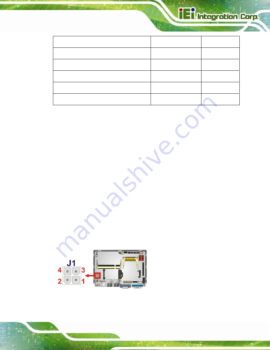
3.3.1 ATX Power Connector
CN Label:
J1
CN Type:
4-pin power connector (1x4)
CN Location:
The 4-pin ATX power connector is connected to a DC-DC power module.
Figure 3-2: ATX Power Connector Location
Содержание ECW-281B-D525
Страница 13: ...ECW 281B B2 D525 Embedded System Page 1 Chapter 1 1 Introduction ...
Страница 20: ...ECW 281B B2 D525 Embedded System Page 8 Chapter 2 2 Mechanical Description ...
Страница 26: ...ECW 281B B2 D525 Embedded System Page 14 Chapter 3 3 System Components ...
Страница 41: ...ECW 281B B2 D525 Embedded System Page 29 Chapter 4 4 Installation ...
Страница 61: ...ECW 281B B2 D525 Embedded System Page 49 Figure 4 20 Power Button ...
Страница 62: ...ECW 281B B2 D525 Embedded System Page 50 5 BIOS Chapter 6 ...
Страница 91: ...ECW 281B B2 D525 Embedded System Page 79 Chapter 6 6 Troubleshooting and Maintenance ...
Страница 97: ...ECW 281B B2 D525 Embedded System Page 85 A Safety Precautions Appendix A ...
Страница 102: ...ECW 281B B2 D525 Embedded System Page 90 B BIOS Menu Options Appendix B ...
Страница 105: ...ECW 281B B2 D525 Embedded System Page 93 C Watchdog Timer Appendix C ...


