


ECW-281B/B2-D525 Embedded System
Page 10
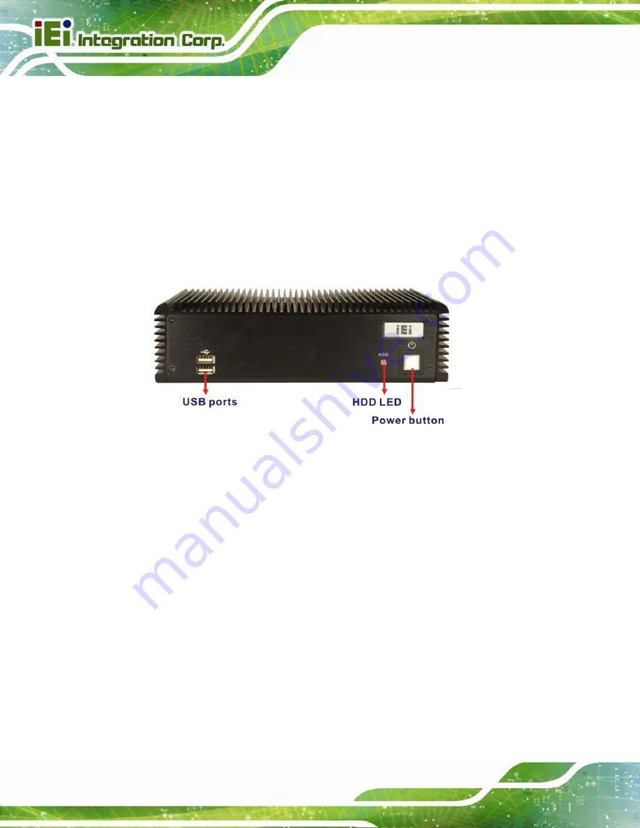
2.3 External Overview
2.3.1 Front Panel
The ECW-281B/B2-D525 front panel contains:
2 x USB port connectors
1 x HDD LED indicator
1 x Power button
An overview of the front panel is shown in
654
Figure 2-2: ECW-281B/B2-D525 Front Panel
2.3.2 Rear Panel
2.3.2.1 ECW-281B-D525 Rear Panel
The rear panel of the ECW-281B-D525 provides access to the following external I/O
connectors.
2 x USB port connectors
2 x RJ-45 Ethernet connector
1 x VGA connector
1 x RS-232 or RS-422/485 (optional) serial port
5 x RS-232 serial ports
1 x Speaker out
1 x 3-pin power terminal block
1 x 12V DC power jack
Содержание ECW-281B-D525
Страница 13: ...ECW 281B B2 D525 Embedded System Page 1 Chapter 1 1 Introduction ...
Страница 20: ...ECW 281B B2 D525 Embedded System Page 8 Chapter 2 2 Mechanical Description ...
Страница 26: ...ECW 281B B2 D525 Embedded System Page 14 Chapter 3 3 System Components ...
Страница 41: ...ECW 281B B2 D525 Embedded System Page 29 Chapter 4 4 Installation ...
Страница 61: ...ECW 281B B2 D525 Embedded System Page 49 Figure 4 20 Power Button ...
Страница 62: ...ECW 281B B2 D525 Embedded System Page 50 5 BIOS Chapter 6 ...
Страница 91: ...ECW 281B B2 D525 Embedded System Page 79 Chapter 6 6 Troubleshooting and Maintenance ...
Страница 97: ...ECW 281B B2 D525 Embedded System Page 85 A Safety Precautions Appendix A ...
Страница 102: ...ECW 281B B2 D525 Embedded System Page 90 B BIOS Menu Options Appendix B ...
Страница 105: ...ECW 281B B2 D525 Embedded System Page 93 C Watchdog Timer Appendix C ...


