


ECN-360A-D2550 Em b e d d e d S ys te m
P a g e 38
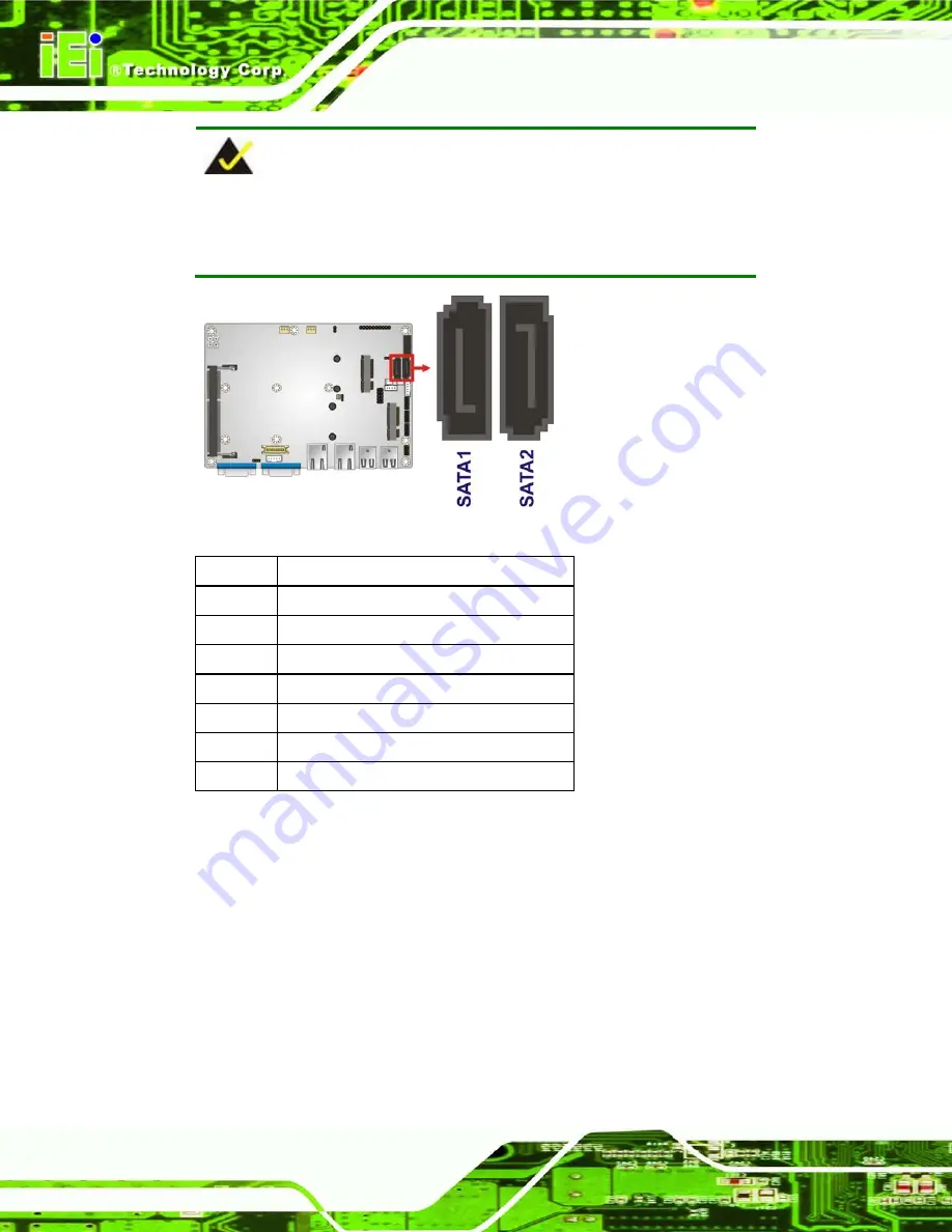
NOTE:
The
SATA1
connector will be disabled when an mSATA device is
installed to the
M_PCIE1
slot.
Figure 4-15: SATA Drive Connector Locations
Pin
Description
1
GND
2
TX+
3
TX-
4
GND
5
RX-
6
RX+
7
GND
Table 4-16: SATA Drive Connector Pinouts
4.2.15
S O-DIMM Co n n e c to r
CN La b e l:
DIMM1
CN Typ e :
204-pin DDR3 SO-DIMM connector
CN Lo c a tio n :
See
The SO-DIMM connector is for installing memory on the system.
Содержание ECN-360A-D2550
Страница 12: ...ECN 360A D2550 Embedded Sys tem Page 1 Chapter 1 1 Introduction...
Страница 17: ...ECN 360A D2550 Embedded Sys tem Page 6 Figure 1 3 ECN 360A D2550 Rear Panel...
Страница 19: ...ECN 360A D2550 Embedded Sys tem Page 8 Chapter 2 2 Unpacking...
Страница 23: ...ECN 360A D2550 Embedded Sys tem Page 12 Chapter 3 3 Ins tallation...
Страница 34: ...ECN 360A D2550 Embedded Sys tem Page 23 Chapter 4 4 Sys tem Motherboard...
Страница 58: ...ECN 360A D2550 Embedded Sys tem Page 47 Chapter 5 5 BIOS...
Страница 86: ...ECN 360A D2550 Embedded Sys tem Page 75 A Safety Precautions Appendix A...
Страница 91: ...ECN 360A D2550 Embedded Sys tem Page 80 B BIOS Menu Options Appendix B...
Страница 94: ...ECN 360A D2550 Embedded Sys tem Page 83 Appendix C C One Key Recovery...
Страница 102: ...ECN 360A D2550 Embedded Sys tem Page 91 Figure C 5 Partition Creation Commands...
Страница 135: ...ECN 360A D2550 Embedded Sys tem Page 124 D Watchdog Timer Appendix D...
Страница 138: ...ECN 360A D2550 Embedded Sys tem Page 127 Appendix E E Hazardous Materials Dis clos ure...


