background image


AFL-AM2 Panel PC 

Page 61

J6 Description 

Open 

Slave 

Closed Master 

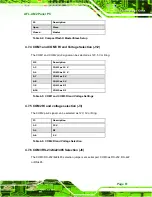
Table 4-4: CompactFlash® Master/Slave Setup 

4.7.4 COM1 and COM3 RI and Voltage Selection (J12) 

The COM1 and COM2 pin-9 signal can be selected as 12V, 5V or Ring. 

J12 Description 

1-3 

COM1 as 12 V 

2-4 

COM2 as 12 V 

5-7 

COM1 as 5 V 

6-8 

COM2 as 5 V 

7-9 COM1 

as 

RI 

8-10 COM2 

as 

RI 

Table 4-5: COM1 and COM3 RI and Voltage Settings 

4.7.5 COM2 RI and voltage selection (J3) 

The COM2 pin-9 signal can be selected as 12V, 5V or Ring. 

J3 Description 

1-2 12 

3-4 

RI 

5-6 5 

Table 4-6: COM2 RI and Voltage Selection 

4.7.6 COM3 RS-232/422/485 Selection (J8) 

The COM3 RS-232/422/485 selection jumper sets serial port COM3 as RS-232, RS-422 

or RS-485. 

Содержание Afolux AFL-15B-AM2

Страница 1: ...AFL AM2 Panel PC Page i...

Страница 2: ...AFL AM2 Panel PC Page ii Revision Date Version Changes June 2008 1 00 Initial release...

Страница 3: ...rising out of the use or inability to use the product or documentation even if advised of the possibility of such damages This document contains proprietary information protected by copyright All righ...

Страница 4: ...e Failure to adhere to warning messages may result in permanent damage to the AFL AM2 or personal injury to the user Please take warning messages seriously CAUTION Cautionary messages should also be h...

Страница 5: ...tained therein can help avoid making mistakes Notes are easy to recognize The word note is written as NOTE both capitalized and bold and is followed by text The text is the cautionary message A note m...

Страница 6: ...d an email to sales iei com tw The items listed below should all be included in the AFL AM2 package 1 x Power cord 1 x Power adapter 1 x User Manual and driver CD 1 x Touch screen pen 1 x Panel mounti...

Страница 7: ...ATIONS 9 2 1 INTRODUCTION 10 2 2 SYSTEM SPECIFICATIONS 10 2 3 DIMENSIONS 12 2 3 1 AFL 15B AM2 Dimensions 12 2 3 2 AFL 17B AM2 Dimensions 14 2 3 3 AFL 19B AM2 Dimensions 16 2 4 CPU SUPPORT 17 2 5 SYSTE...

Страница 8: ...6 HSDPA MODULE INSTALLATION 32 3 7 HDD INSTALLATION 33 3 8 AT ATX MODE SELECTION 36 3 8 1 AT Power Mode 36 3 8 2 ATX Power Mode 37 3 9 MOUNTING THE SYSTEM 37 3 9 1 Wall Mounting 38 3 9 2 Panel Mounti...

Страница 9: ...ction J5 62 4 7 8 COM3 Terminator Setting J10 J14 62 4 7 9 COM3 Mode Selection Jumper J11 62 4 7 10 LCD Type Selection PA_ID1 63 4 7 11 LCD Voltage Setup J1 63 4 7 12 Touch Panel Setup J4 63 5 BIOS SE...

Страница 10: ...8 5 8 POWER 110 5 9 EXIT 113 6 SOFTWARE DRIVERS 115 6 1 AVAILABLE SOFTWARE DRIVERS 116 6 2 DRIVER CD AUTO RUN 116 6 3 AMD SB600 CHIPSET DRIVER INSTALLATION 118 6 4 BROADCOM LAN DRIVER FOR GBE LAN INST...

Страница 11: ...TOUCH PANEL DRIVER 146 D 2 1 Introduction 146 D 2 2 Driver Installation 146 D 2 3 Touch Panel Driver Configuration 150 E WATCHDOG TIMER 151 F HAZARDOUS MATERIALS DISCLOSURE 154 F 1 HAZARDOUS MATERIAL...

Страница 12: ...s in mm 17 Figure 2 7 SO DIMM Socket 20 Figure 2 8 CompactFlash Slot 21 Figure 2 9 SATA Hard Drive Slot 22 Figure 2 10 Bluetooth Module 22 Figure 2 11 HSDPA Module 23 Figure 2 12 Wireless LAN Module 2...

Страница 13: ...Removal 54 Figure 4 3 Heatsink Screws 54 Figure 4 4 CPU Heatsink 55 Figure 4 5 Install the CPU 56 Figure 4 6 SO DIMM Socket Location 57 Figure 4 7 DDR2 SO DIMM Module Installation 58 Figure 4 8 Serial...

Страница 14: ...gure 6 19 Select the Audio CODEC 128 Figure 6 20 Locate the Setup Program Icon 129 Figure 6 21 Preparing Setup Screen 129 Figure 6 22 InstallShield Wizard Welcome Screen 130 Figure 6 23 Audio Driver S...

Страница 15: ...4 4 CompactFlash Master Slave Setup 61 Table 4 5 COM1 and COM3 RI and Voltage Settings 61 Table 4 6 COM2 RI and Voltage Selection 61 Table 4 7 COM3 RS 232 422 485 Selection 62 Table 4 8 COM3 RS 422 4...

Страница 16: ...nfiguration 89 BIOS Menu 11 USB Mass Storage Device Configuration 91 BIOS Menu 12 PCI PnP Configuration 93 BIOS Menu 13 Boot 95 BIOS Menu 14 Boot Settings Configuration 96 BIOS Menu 15 Boot Device Pri...

Страница 17: ...AFL AM2 Panel PC Page 1 Chapter 1 1 Introduction...

Страница 18: ...ral interface connectors The integrated wireless LAN module provides a wireless connection to a network and the Bluetooth module ensures an uninterrupted wireless connection to connected Bluetooth dev...

Страница 19: ...tions include Vehicle Interior device o Truck PC o Logistic car PC General computing o PC based testing center o Distance learning Industrial applications o Plant environment monitoring system o Facto...

Страница 20: ...tion process RoHS compliance 1 2 External Overview The AFL AM2 is a flat panel PC The monitor and all internal components are enclosed in an aluminum chassis An ABS PC plastic cover surrounds the alum...

Страница 21: ...AFL AM2 Panel PC Page 5 1 2 1 Front Panel The front side of the AFL AM2 is a flat panel TFT LCD screen surrounded by an ABS PC plastic frame Figure 1 2 Front View...

Страница 22: ...1 3 Rear View 1 2 3 Bottom Panel The bottom panel of the AFL AM2 has the following I O interfaces Figure 1 4 1 x External SATA port 1 x RS 232 serial port connector 1 x RS 232 422 485 serial port con...

Страница 23: ...view The AFL AM2 includes the following parts inside the aluminum internal cover AMD Athlon 64 X2 dual core processor 1 0 GB DDR2 SO DIMM Antennas Backlight inverter Bluetooth module CompactFlash disk...

Страница 24: ...AFL AM2 Panel PC Page 8 Figure 1 5 Internal Overview...

Страница 25: ...AFL AM2 Panel PC Page 9 Chapter 2 2 Specifications...

Страница 26: ...low 2 2 System Specifications The technical specifications for the AFL AM2 systems are listed in Table 2 1 SPECIFICATION 15 inch 17 inch 19 inch LCD Size 15 17 19 Max Resolution 1024 x 768 1280 x 1024...

Страница 27: ...ED Functions 1 x Power on off LED Mounting VESA MIS D mount for panel wall rack not for 19 inch model stand and arm mounting Front Panel Color Silver Dimensions W x H x D mm 393 06 x 308 06 x 74 6 428...

Страница 28: ...AFL AM2 Panel PC Page 12 2 3 Dimensions 2 3 1 AFL 15B AM2 Dimensions The dimensions of the AFL 15B AM2 flat panel PC are shown in Figure 2 1 below Figure 2 1 AFL 15B AM2 Front Dimensions units in mm...

Страница 29: ...AFL AM2 Panel PC Page 13 Figure 2 2 AFL 15B AM2 Rear Dimensions units in mm...

Страница 30: ...AFL AM2 Panel PC Page 14 2 3 2 AFL 17B AM2 Dimensions The dimensions of the AFL 17B AM2 flat panel PC are shown in Figure 2 3 below Figure 2 3 AFL 17B AM2 Front Dimensions units in mm...

Страница 31: ...AFL AM2 Panel PC Page 15 Figure 2 4 AFL 17B AM2 Rear Dimensions units in mm...

Страница 32: ...AFL AM2 Panel PC Page 16 2 3 3 AFL 19B AM2 Dimensions The dimensions of the AFL 19B AM2 flat panel PC are shown in Figure 2 3 below Figure 2 5 AFL 19B AM2 Front Dimensions units in mm...

Страница 33: ...AM2 CPU socket and supports AMD Athlon 64 X2 Dual Core processors up to 5200 Some of the specifications of these processors are listed below Two processing cores True multitasking allowing quick switc...

Страница 34: ...d 128 bit engine capable of processing four pixels per clock Supports a maximum resolution of 2048 x 1536 32bpp Game acceleration including support for Microsoft s DirectDraw The AMD M690T also has th...

Страница 35: ...nel with DMA support up to DMA 133 Audio link compliant with AC 97 rev 2 3 Two cascaded 8237 DMA controllers 2 6 Graphics Support The ATi M690T Northbridge chipset has an integrated graphics engine th...

Страница 36: ...ry All processors supported by the AFL AM2 have their own internal DDR2 memory controller The DDR2 controller has the following features Low latency high bandwidth 800 MHz 128 bit DDR2 SDRAM controlle...

Страница 37: ...sh slot location is shown below Figure 2 8 CompactFlash Slot 2 8 2 SATA Hard Drive The integrated SATA controller supports two SATA drives with independent DMA operations One SATA port is implemented...

Страница 38: ...uetooth module enables the transmission between various peripheral devices through a Bluetooth network Figure 2 10 Bluetooth Module Bluetooth enabled peripheral devices include Headsets Barcode reader...

Страница 39: ...nal The HSDPA module is one of the OEM options for the AFL AM2 Figure 2 11 HSDPA Module The HSDPA module connects to 3G and 3 5G cellular networks The connectivity provided by the HSDPA module allows...

Страница 40: ...module are listed below Compliant with IEEE 802 11a 802 11b and 802 11g standards USB 2 0 interface via the PCIe Mini slot VIA Solomon VT6656 wireless LAN controller 2 12 Gigabit Ethernet The Broadco...

Страница 41: ...he tough construction of the TFT monitor allows the AFL AM2 to withstand the conditions it is likely to be exposed to during regular use Some of the specifications of the TFT monitors are shown below...

Страница 42: ...4 OEM Options Some of the peripheral device connectors are not connected to any devices These connectors are reserved for OEM customizations For a customized option please contact the vendor reseller...

Страница 43: ...AFL AM2 Panel PC Page 27 Chapter 3 3 Installation...

Страница 44: ...people are assisting with the procedure Anti static Discharge If a user open the rear panel of the flat panel PC to configure the jumpers or plug in added peripheral devices ground themselves first a...

Страница 45: ...flat panel PC follow the steps below WARNING The front side LCD screen has a protective plastic cover stuck to the screen Only remove the plastic cover after the flat panel PC has been properly instal...

Страница 46: ...flat panel PC Step 7 Make sure all the components listed in the packing list are present 3 4 1 Packing List The AFL AM2 flat panel PC is shipped with the following components Quantity Item Image Stan...

Страница 47: ...of these items are missing or damaged contact the distributor or sales representative immediately 3 5 CompactFlash Card Installation The AFL AM2 has one CompactFlash Type I II slot inside the rear pa...

Страница 48: ...k cover and fasten the retention screws Step 0 3 6 HSDPA Module Installation The HSDPA module attaches to a USB type A receptacle located under the back cover of the AFL AM2 To install the HSDPA modul...

Страница 49: ...re drivers for the HSDPA module are included with the HSDPA module 3 7 HDD Installation To install the hard drive please follow the steps below Step 1 Disconnect the system power cable Step 2 Remove t...

Страница 50: ...Remove the four HDD bracket retention screws Figure 3 6 and lift the HDD bracket off the panel PC Figure 3 6 AFL AM2 Hard Drive Bracket Retention Screws Step 6 Attach the hard drive to the hard drive...

Страница 51: ...gure 3 7 Hard Drive Retention Screws Step 7 Reinstall the hard drive bracket Slide the hard drive bracket into its original position making sure the SATA connectors on the hard drive connect with the...

Страница 52: ...move the plastic back cover See Section 3 5 above Step 2 Locate the AT ATX switch at the bottom right on the aluminum chassis Figure 3 9 Figure 3 9 AT ATX Switch Location Step 3 Adjust the AT ATX swit...

Страница 53: ...since the broadcasting time for each panel PC can be set individually and controlled remotely Other possible applications include Security surveillance Point of Sale POS Advertising terminal 3 9 Mount...

Страница 54: ...ep 4 Align the wall mounting bracket screw holes with the pilot holes Step 5 Secure the mounting bracket to the wall by inserting the retention screws into the four pilot holes and tightening them Fig...

Страница 55: ...rely in the slotted holes Figure 3 11 Ensure that all four of the mounting screws fit snuggly into their respective slotted holes Figure 3 11 Chassis Support Screws NOTE In the diagram below the brack...

Страница 56: ...panel to mount the flat panel PC Step 2 Cut out a section from the panel that corresponds to the rear panel dimensions of the flat panel PC Take care that the panel section that is cut out is smaller...

Страница 57: ...AFL AM2 Panel PC Page 41 Figure 3 13 AFL 15B AM2 Cutout Dimensions units in mm Figure 3 14 AFL 17B AM2 Cutout Dimensions units in mm...

Страница 58: ...minum frame is flush against the panel Step 4 Insert the panel mounting clamps into the pre formed holes along the edges of the chassis behind the aluminum frame Step 5 Tighten the screws that pass th...

Страница 59: ...on an arm please follow the steps below Step 1 The arm is a separately purchased item Please correctly mount the arm onto the surface it uses as a base To do this refer to the installation documentati...

Страница 60: ...s shown in Figure 3 17 Figure 3 17 Arm Mounting Retention Screw Holes Step 4 Secure the flat panel PC to the interface pad by inserting four retention screws through the bottom of the mounting arm int...

Страница 61: ...C through the rack cabinet bracket until the aluminum frame is flush against the front of the bracket Figure 3 18 Figure 3 18 The Rack Cabinet Bracket Step 2 Insert the rack mounting clamps into the p...

Страница 62: ...Panel PC Page 46 Figure 3 19 Secure the Rack Cabinet Bracket Step 4 Slide the flat panel PC with the attached rack cabinet bracket into a rack or cabinet Figure 3 20 Figure 3 20 Install into a Rack C...

Страница 63: ...located at the bottom of the rear panel on the AFL AM2 panel PC 3 10 1 LAN Connection There are two external RJ 45 LAN connectors The RJ 45 connectors enable connection to an external network To conne...

Страница 64: ...steps below to connect a serial device to the AFL AM2 panel PC Step 1 Locate the DB 9 connector The location of the DB 9 connector is shown in Chapter 2 Step 2 Insert the serial connector Insert the D...

Страница 65: ...ow the instructions below Step 1 Locate the USB connectors The locations of the USB connectors are shown in Chapter 2 Step 2 Align the connectors Align the USB device connector with one of the connect...

Страница 66: ...n in Chapter 3 Step 2 Align the VGA connector Align the male DB 15 connector on the VGA screen cable with the female DB 15 connector on the external peripheral interface Step 3 Insert the VGA connecto...

Страница 67: ...AFL AM2 Panel PC Page 51 Chapter 4 4 System Maintenance...

Страница 68: ...s failed please contact the system vendor reseller or an IEI sales person directly 4 3 Internal Aluminum Cover Removal WARNING Turn the power off before removing the back cover Failing to do so may le...

Страница 69: ...Screw positions are indicated below Figure 4 1 Figure 4 1 AFL 19B AM2 Aluminum Back Cover Retention Screws 4 4 CPU Replacement The CPU is preinstalled If the CPU needs to be replaced because it fails...

Страница 70: ...rews Locate the CPU fan power cable and detach it from the fan power wafer on the motherboard Unscrew the four retaining screws holding the CPU heatsink in place The heatsink screws are the four large...

Страница 71: ...S t e p 0 Figure 4 4 CPU Heatsink 4 4 2 Socket AM2 CPU Installation WARNING CPUs are expensive and sensitive components When installing the CPU please be careful not to damage it in anyway Make sure t...

Страница 72: ...Disengage the load lever by moving the lever slightly outward to clear the retention tab Rotate the load lever to a fully open position See Figure 4 5 Step 3 Orientate the CPU properly Make sure the I...

Страница 73: ...n 4 3 above Step 3 Locate the DDR2 memory module on the motherboard of the flat panel PC Figure 4 6 Figure 4 6 SO DIMM Socket Location Step 4 Remove the DDR2 memory module by pulling both the spring r...

Страница 74: ...Type DB9 connectors CN Pinouts See Table 4 1 and Figure 4 8 COM1 supports RS 232 COM3 supports RS 232 RS 422 and RS 485 Pinouts for RS 232 RS 422 and RS 485 are shown below these apply to all serial p...

Страница 75: ...ectrical circuit It consists of two metal pins and a small metal clip often protected by a plastic cover that slides over the pins to connect them To CLOSE SHORT a jumper means connecting the pins of...

Страница 76: ...r Selection Jumper J13 This jumper is connected to the AT ATX selection switch on the rear of the AFL AM2 J13 Description Closed ATX Power Open AT Power Table 4 2 AT ATX Power Selection Jumper 4 7 2 C...

Страница 77: ...OM1 as 12 V 2 4 COM2 as 12 V 5 7 COM1 as 5 V 6 8 COM2 as 5 V 7 9 COM1 as RI 8 10 COM2 as RI Table 4 5 COM1 and COM3 RI and Voltage Settings 4 7 5 COM2 RI and voltage selection J3 The COM2 pin 9 signal...

Страница 78: ...e COM3 terminator jumpers are for terminating an RS 422 or RS 485 setup The default setting is for both J10 and J14 to be open To remedy transmission problems with cables over 1 5 km in length try set...

Страница 79: ...6 9 10 1280 x 1024 48 bit 1 2 5 6 9 10 1600 x 1200 48 bit 3 4 5 6 9 10 1600 x 1200 36 bit 1 2 3 4 5 6 9 10 1366 x 768 18 bit Table 4 11 LCD Type Selection 4 7 11 LCD Voltage Setup J1 This jumper shoul...

Страница 80: ...AFL AM2 Panel PC Page 64 J4 Description 3 4 SENSE Table 4 13 LCD Type Selection...

Страница 81: ...AFL AM2 Panel PC Page 65 Chapter 5 5 BIOS Setup...

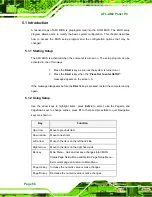
Страница 82: ...e appears on the screen 0 If the message disappears before the DELETE key is pressed restart the computer and try again 5 1 2 Using Setup Use the arrow keys to highlight items press ENTER to select us...

Страница 83: ...ion Changes If the computer cannot boot after changes to the system configuration is made CMOS defaults Use the jumper described in Chapter 5 5 1 5 BIOS Menu Bar The menu bar on top of the BIOS screen...

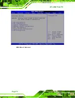
Страница 84: ...ifferent system components The fields in System Overview cannot be changed The items shown in the system overview include AMI BIOS Displays auto detected BIOS information o Version Current BIOS versio...

Страница 85: ...tem Date option to set the system date Manually enter the day month and year 5 3 Advanced Use the Advanced menu to configure the CPU and peripheral devices through the following sub menus WARNING Sett...

Страница 86: ...AFL AM2 Panel PC Page 70 BIOS Menu 2 Advanced...

Страница 87: ...S Menu 3 lists the following CPU details Revision Lists the CPU revision number Cache L1 Lists the CPU L1 cache size Cache L2 Lists the CPU L2 cache size Speed Lists the CPU processing speed Current F...

Страница 88: ...onfiguration OnBoard PCI IDE Controller Primary The OnBoard PCI IDE Controller BIOS option specifies the IDE channels used by the onboard PCI IDE controller The following configuration options are ava...

Страница 89: ...in the IDE Configuration menu Primary IDE Master Primary IDE Slave Secondary IDE Master Secondary IDE Slave Third IDE Master Third IDE Slave The IDE Configuration menu BIOS Menu 4 allows changes to t...

Страница 90: ...ayed out items in the left frame are IDE disk drive parameters automatically detected from the firmware of the selected IDE disk drive The drive parameters are listed as follows Device Lists the devic...

Страница 91: ...2Bit Data Transfer Enables 32 bit data transfer Type Auto Use the Type BIOS option select the type of device the AMIBIOS attempts to boot from after the Power On Self Test POST is complete Not Install...

Страница 92: ...lti Sector Transfer on the specified channel The data to and from the device occurs one sector at a time Auto DEFAULT BIOS auto detects Multi Sector Transfer support on the drive on the specified chan...

Страница 93: ...DMA mode 0 selected with a maximum data transfer rate of 2 1 MB s SWDMA1 Single Word DMA mode 1 selected with a maximum data transfer rate of 4 2 MB s SWDMA2 Single Word DMA mode 2 selected with a max...

Страница 94: ...R T Auto Use the S M A R T option to auto detect disable or enable Self Monitoring Analysis and Reporting Technology SMART on the drive on the specified channel S M A R T predicts impending drive fail...

Страница 95: ...guration Serial Port1 Address 3F8 IRQ4 Use the Serial Port1 Address option to select the Serial Port 1 base address Disabled No base address is assigned to Serial Port 1 3F8 IRQ4 DEFAULT Serial Port 1...

Страница 96: ...rial Port3 Address option to select the Serial Port 3 base address Disabled No base address is assigned to Serial Port 3 3E8 DEFAULT Serial Port 3 I O port address is 3E8 2E8 Serial Port 3 I O port ad...

Страница 97: ...rt 4 I O port address is 338 238 Serial Port 4 I O port address is 238 5 3 4 Hardware Health Configuration The Hardware Health Configuration menu BIOS Menu 7 shows the operating temperature fan speeds...

Страница 98: ...pe PWM x When the FAN x Mode Setting option is in the PWM Manual Mode the following parameters can be set Fan x PWM control Temperature x Limit of OFF 000 WARNING Setting this value too high may cause...

Страница 99: ...odulation PWM specified in the Fan x Start PWM option below To select a value select the Temperature x Limit of Start option and enter a decimal number between 000 and 127 The temperature range is spe...

Страница 100: ...ptions is shown below 0 PWM 1 PWM 2 PWM 4 PWM 8 PWM 16 PWM 32 PWM 64 PWM The following system parameters and values are shown The system parameters that are monitored are System Temperatures The follo...

Страница 101: ...e S1 POS Use the Suspend Mode option to specify the sleep state the system enters when it is not being used S1 POS DEFAULT Suspend mode puts the system into an S1 sleep state A system in S1 sleep stat...

Страница 102: ...takes longer to wake up 5 3 6 Remote Access Configuration Use the Remote Access Configuration menu BIOS Menu 9 to configure remote access parameters The Remote Access Configuration is an AMIBIOS feat...

Страница 103: ...r remote access COM1 DEFAULT System is remotely accessed through COM1 COM2 System is remotely accessed through COM2 COM3 System is remotely accessed through COM3 NOTE Make sure the selected COM port i...

Страница 104: ...when console redirection should occur Disabled The console is not redirected after POST Boot Loader Redirection is active during POST and during Boot Loader Always DEFAULT Redirection is always active...

Страница 105: ...Menu 10 USB Configuration USB 1 1 OHCI Controller Enabled The USB 1 1 OHCI Controller BIOS option enables or disables the USB 1 1 controller Disabled USB 1 1 function disabled Enabled Default USB 1 1...

Страница 106: ...there is no USB driver loaded onto the system Disabled Legacy USB support disabled Enabled DEFAULT Legacy USB support enabled Auto Legacy USB support disabled if no USB devices are connected USB2 0 Co...

Страница 107: ...storage device after the start unit command 10 Sec POST waits 10 seconds for the USB mass storage device after the start unit command 20 Sec DEFAULT POST waits 20 seconds for the USB mass storage dev...

Страница 108: ...setup The FORMAT utility provided by Microsoft MS DOS Microsoft Windows 95 and Microsoft Windows 98 can be used for this purpose Auto DEFAULT BIOS auto detects the current USB Floppy The USB device w...

Страница 109: ...etting wrong values for the BIOS selections in the PCIPnP BIOS menu may cause the system to malfunction BIOS Menu 12 PCI PnP Configuration IRQ Available Use the IRQ address to specify what IRQs can be...

Страница 110: ...15 DMA Channel Available Use the DMA Channel option to assign a specific DMA channel to a particular PCI PnP device Available DEFAULT The specified DMA is available to be used by PCI PnP devices Rese...

Страница 111: ...that should be reserved for legacy ISA devices Disabled DEFAULT No memory block reserved for legacy ISA devices 16K 16KB reserved for legacy ISA devices 32K 32KB reserved for legacy ISA devices 64K 6...

Страница 112: ...Configuration Quick Boot Enabled Use the Quick Boot BIOS option to make the computer speed up the boot process Disabled No POST procedures are skipped Enabled DEFAULT Some POST procedures are skipped...

Страница 113: ...oard Number Lock automatically To use the 10 keys on the keyboard press the Number Lock key located on the upper left hand corner of the 10 key pad The Number Lock LED on the keyboard lights up when t...

Страница 114: ...ilable devices The following options are available 1st Boot Device 2nd Boot Device BIOS Menu 15 Boot Device Priority Settings 5 5 3 Hard Disk Drives Use the Hard Disk Drives menu to specify the boot s...

Страница 115: ...evices is selected If the 1st Drive option is selected a list of available HDDs is shown Select the first HDD the system boots from If the 1st Drive is not used for booting this option may be disabled...

Страница 116: ...or USB is connected only 1st Drive is listed The boot sequence from the available devices is selected If the 1st Drive option is selected a list of available FDDs and USB devices is shown Select the...

Страница 117: ...Installed If a supervisor password must be installed select this field and enter the password After the password has been added Install appears next to Change Supervisor Password Change User Password...

Страница 118: ...set Use the Chipset menu to access the Northbridge and Southbridge configuration menus WARNING Setting the wrong values for the Chipset BIOS selections in the Chipset BIOS menu may cause the system to...

Страница 119: ...g Northbridge chipset settings Memory CLK Shows the speed of the memory controller CAS Latency Specifies the Column Address Strobe CAS delay time RAS CAS Delay Trcd Specifies the number of clock cycle...

Страница 120: ...set the ECC parameters BIOS Menu 21 ECC Configuration Chipset Configuration DRAM ECC Enable Enabled Use the DRAM ECC Enable option to enable the hardware to report and correct memory errors and thereb...

Страница 121: ...bled System cannot immediately correct DRAM ECC errors DRAM BG Scrub Disabled Use the DRAM BG Scrub option to enable the system to immediately correct memory errors so later reads are correct Doing th...

Страница 122: ...ble the system to correct the L1 Data cache when idle Disabled Default L1 cache can be corrected when the system is idle Enabled L1 cache cannot be corrected when the system is idle 5 7 3 Internal Gra...

Страница 123: ...hics can only access a dynamically allocated partition of system memory UMA Buffer Size Auto Use the UMA Buffer Size option to specify the memory to be reserved for the integrated graphics The followi...

Страница 124: ...Chipset Configuration AC 97 Audio Device Disabled Use the AC 97 Audio Device option to enable or disable the AC 97 CODEC Auto DEFAULT The onboard audio is turned on Disabled The onboard audio is turne...

Страница 125: ...led Use the OnChip SATA option to enable or disable the SATA controller on the Southbridge Enabled DEFAULT Enables the Southbridge SATA controller Disabled Disables the Southbridge SATA controller OnC...

Страница 126: ...Menu 24 Power AT ATX Power ATX Use the AT ATX Power BIOS option to select the power supply that is connected to the system AT An AT power supply is connected to the system ATX DEFAULT An ATX power su...

Страница 127: ...Keyboard Mouse Disabled Use the Resume on Keyboard Mouse BIOS option to enable activity on either the keyboard or mouse to rouse the system from a suspend or standby state That is the system is rouse...

Страница 128: ...be roused from a suspended state Disabled DEFAULT The real time clock RTC cannot generate a wake event Enabled If selected the following appears with values that can be selected RTC Alarm Date Days S...

Страница 129: ...Save Changes and Exit option to save the changes made to the BIOS options and to exit the BIOS configuration setup program Discard Changes and Exit Use the Discard Changes and Exit option to exit the...

Страница 130: ...ad the optimal default values for each of the parameters on the Setup menus F9 key can be used for this operation Load Failsafe Defaults Use the Load Failsafe Defaults option to load failsafe default...

Страница 131: ...AFL AM2 Panel PC Page 115 Chapter 6 6 Software Drivers...

Страница 132: ...m LAN driver HD Audio Kit Driver Installation Installation instructions are given below 6 2 Driver CD Auto run All the drivers for the AFL AM2 are on the CD that came with the system To install the dr...

Страница 133: ...reen Step 3 Click AFL AM2 Step 4 A new screen with a list of available drivers appears Figure 6 2 Figure 6 2 Available Drivers Step 5 Select the driver to install from the list in Figure 6 2 Detailed...

Страница 134: ...lows a user to control the configuration of the AMD product To verify NET Framework check the Add Remove Programs list in the Control Panel If the NET Framework is not listed please download and insta...

Страница 135: ...Chipset Driver Installation Welcome Screen Step 5 Open the SB600 directory The screen in Figure 6 5 appears Figure 6 5 Chipset Driver Installation License Agreement Step 6 The screen in Figure 6 6 ap...

Страница 136: ...6 6 Select Destination Folder Step 7 Click install to continue Step 8 The screen in Figure 6 7 appears as the driver starts to install Figure 6 7 Chipset Driver Installing Screen Step 9 The welcome sc...

Страница 137: ...re 6 8 Welcome Screen Step 10 Click YES to continue Step 11 The License agreement file in Figure 6 9 appears Figure 6 9 Chipset Driver Readme File Information Step 12 Click YES to continue Step 13 The...

Страница 138: ...t to continue Step 15 The installer starts to load the display driver Step 16 Next the WDM Capture drivers load for VIVO or All In Wonder Step 17 The Catalyst Control Center setup starts shortly after...

Страница 139: ...Step 20 To complete the installation click Finish Step 0 6 4 Broadcom LAN Driver for GbE LAN Installation To install the Broadcom LAN driver please follow the steps below Step 1 Open Windows Control...

Страница 140: ...AFL AM2 Panel PC Page 124 Step 2 Double click the System icon Figure 6 13 Figure 6 13 System Icon Step 3 Click the Device Manager tab Figure 6 14 Figure 6 14 Device Manager Tab...

Страница 141: ...appears Figure 6 15 Figure 6 15 Device Manager List Step 5 Double click the listed device that has question marks next to it this means Windows does not recognize the device Step 6 The Device Driver...

Страница 142: ...device recommended and click NEXT to continue Step 8 Select Specify a Location in the Locate Driver Files window Figure 6 17 Figure 6 17 Locate Driver Files Step 9 Click NEXT to continue Step 10 The...

Страница 143: ...7 audio driver please follow the steps below 6 5 1 BIOS Setup Step 1 Enter the BIOS setup To do this reboot the system and press DEL during POST Step 2 Go to the Southbridge Configuration menu Set the...

Страница 144: ...AFL AM2 Panel PC Page 128 Figure 6 19 Select the Audio CODEC Step 3 Double click the ALC665 folder Step 4 Double click the Setup exe program icon in Figure 6 20...

Страница 145: ...he Setup Program Icon Step 5 The InstallShield Wizard is prepared to guide the user through the rest of the process Figure 6 21 Figure 6 21 Preparing Setup Screen Step 6 Once initialized the InstallSh...

Страница 146: ...Screen Step 7 Click NEXT to continue the installation Step 8 InstallShield starts to install the new software as shown in Figure 6 23 Figure 6 23 Audio Driver Software Configuration Step 9 At this sta...

Страница 147: ...24 Audio Driver Digital Signal Step 10 Click YES and the driver installation begins Figure 6 25 Figure 6 25 Audio Driver Installation Step 11 After the driver installation process is complete a confi...

Страница 148: ...gure 6 26 Restart the Computer Step 12 The confirmation screen offers the option of restarting the computer now or later For the settings to take effect the computer must be restarted Click FINISH to...

Страница 149: ...AFL AM2 Panel PC Page 133 Appendix A A Safety Precautions...

Страница 150: ...onnected whenever the AFL AM2 is being installed moved or modified Do not apply voltage levels that exceed the specified voltage range Doing so may cause fire and or an electrical shock Electric shock...

Страница 151: ...electrical component touch any grounded conducting material During the time the electrical component is handled frequently touch any conducting materials that are connected to the ground Use an anti...

Страница 152: ...y mentioned in the cleaning tips Below is a list of items to use when cleaning the AFL AM2 Cloth Although paper towels or tissues can be used a soft clean piece of cloth is recommended when cleaning t...

Страница 153: ...AFL AM2 Panel PC Page 137 Appendix B B BIOS Configuration Options...

Страница 154: ...O Mode Auto 76 DMA Mode Auto 77 S M A R T Auto 78 32Bit Data Transfer Enabled 78 Serial Port1 Address 3F8 IRQ4 79 Serial Port2 Address 2F8 IRQ3 80 Serial Port3 Address 3E8 80 Select RS232 or RS422 485...

Страница 155: ...Num Lock On 97 Boot From LAN Support Disabled 97 Change Supervisor Password 101 Change User Password 101 DRAM ECC Enable Enabled 104 4 Bit ECC Mode 105 DRAM SCRUB REDIRECT Disabled 105 DRAM BG Scrub...

Страница 156: ...AM2 Panel PC Page 140 Resume on Ring Disabled 111 RTC Resume Disabled 112 Save Changes and Exit 113 Discard Changes and Exit 113 Discard Changes 113 Load Optimal Defaults 114 Load Failsafe Defaults 1...

Страница 157: ...AFL AM2 Panel PC Page 141 Appendix C C Terminology...

Страница 158: ...inary 0 while a high amplitude signal represents a binary 1 BIOS The Basic Input Output System BIOS is firmware that is first run when the computer is turned on and can be configured by the end user C...

Страница 159: ...ep Technology EIST allows users to modify the power consumption levels and processor performance through application software The application software changes the bus to core frequency ratio and the p...

Страница 160: ...sfers between storage devices and the computer chipsets The SATA bus has transfer speeds up to 1 5 Gbps and the SATA II bus has data transfer speeds of up to 3 0 Gbps S M A R T Self Monitoring Analysi...

Страница 161: ...AFL AM2 Panel PC Page 145 Appendix D D Software Drivers...

Страница 162: ...ire five wire eight wire models The controller directly communicates with the PC system through the touch panel communications interface The controller design is superior in sensitivity accuracy and f...

Страница 163: ...the system from the menu on the screen NOTE The following description is for driver installation using a Windows 2000 OS If a different OS is installed please refer to the driver user manual for the r...

Страница 164: ...tep 5 The license agreement shown in Figure C 3 appears Agree to the license by selecting I accept the terms in the license agreement Figure C 3 License Agreement Step 6 Click NEXT and the Installshie...

Страница 165: ...talling PenMount DMC9000 screen appears as the program is installed Figure C 5 Figure C 5 Installing PenMount DMC9000 Step 8 The user is then prompted to select to restart the computer now or later Fi...

Страница 166: ...2 Panel PC Page 150 Figure C 6 Reboot the Computer D 2 3 Touch Panel Driver Configuration To configure the touch panel driver options refer to the PenMount user manual located on the driver installati...

Страница 167: ...AFL AM2 Panel PC Page 151 Appendix E E Watchdog Timer...

Страница 168: ...function call INT 15H is used to control the Watchdog Timer INT 15H AH 6FH Sub function AL 2 Sets the Watchdog Timer s period BL Time out value Its unit second is dependent on the item Watchdog Timer...

Страница 169: ...stem resets Example program INITIAL TIMER PERIOD COUNTER W_LOOP MOV AX 6F02H setting the time out value MOV BX 05 time out value is 5 seconds INT 15H ADD THE APPLICATION PROGRAM HERE CMP EXIT_AP 1 is...

Страница 170: ...AFL AM2 Panel PC Page 154 Appendix F F Hazardous Materials Disclosure...

Страница 171: ...sences of small quantities of certain materials in the product and is applicable to China RoHS only A label will be placed on each product to indicate the estimated Environmentally Friendly Use Period...

Страница 172: ...oard X O O O O X Metal Fasteners X O O O O O Cable Assembly X O O O O X Fan Assembly X O O O O X Power Supply Assemblies X O O O O X Battery O O O O O O O This toxic or hazardous substance is containe...

Страница 173: ...AFL AM2 Panel PC Page 157 RoHS RoHS Pb Hg Cd CR VI PBB PBDE X O O O O X X O O O O X X O O O O X X O O O O O X O O O O X X O O O O X X O O O O X O O O O O O O SJ T11363 2006 X SJ T11363 2006...

Страница 174: ...AFL AM2 Panel PC Page 158 Index...

Страница 175: ...93 102 113 Bluetooth module 22 bracket 34 38 39 45 46 47 C CD drive 147 chipset driver 118 CompactFlash 21 socket 21 cooling fan 84 CPU installation 55 D DB 15 connector 50 DB 9 connector 48 Dimensio...

Страница 176: ...Serial Device connection 48 serial port 6 SO DIMM 57 58 system voltages 81 84 T temperature 81 Touch screen 10 U USB 89 90 external USB device connection 49 USB 2 0 6 89 USB device connection 49 singl...

Отзывы: