


AFL3-W07A-BT Panel PC
Page 77
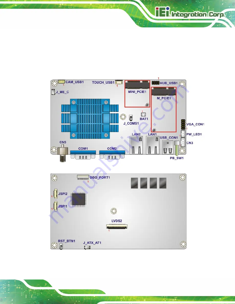
6.1 Peripheral Interface Connectors
The AFL3-W07A-BT panel PC motherboard comes with a number of peripheral interface
connectors and configuration jumpers. The connector locations are shown in
The Pin 1 locations of the on-board connectors are also indicated in the diagram below.
The connector pinouts for these connectors are listed in the following sections.
Figure 6-1: Main Board Layout Diagram (Front Side)
Figure 6-2: Main Board Layout Diagram (Solder Side)
Содержание AFL3-W07A-BT-N1/PC/2G-R20
Страница 13: ...AFL3 W07A BT Panel PC Page 1 1 Introduction Chapter 1 ...
Страница 21: ...AFL3 W07A BT Panel PC Page 9 2 Unpacking Chapter 2 ...
Страница 25: ...AFL3 W07A BT Panel PC Page 13 3 Installation Chapter 3 ...
Страница 54: ...AFL3 W07A BT Panel PC Page 42 4 BIOS Setup Chapter 4 ...
Страница 82: ...AFL3 W07A BT Panel PC Page 70 5 System Maintenance Chapter 5 ...
Страница 88: ...AFL3 W07A BT Panel PC Page 76 6 Interface Connectors Chapter 6 ...
Страница 99: ...AFL3 W07A BT Panel PC Page 87 Appendix A A Regulatory Compliance ...
Страница 104: ...AFL3 W07A BT Panel PC Page 92 B Safety Precautions Appendix B ...
Страница 109: ...AFL3 W07A BT Panel PC Page 97 C BIOS Menu Options Appendix C ...
Страница 112: ...AFL3 W07A BT Panel PC Page 100 Appendix D D Watchdog Timer ...
Страница 115: ...AFL3 W07A BT Panel PC Page 103 E Hazardous Materials Disclosure Appendix E ...