


AFL3-W07A-BT Panel PC
Page 34
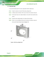
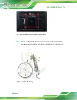
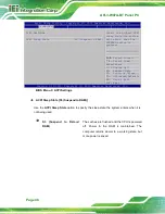
Figure 3-22: Drill Pilot Holes for V-Stand
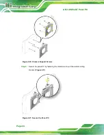
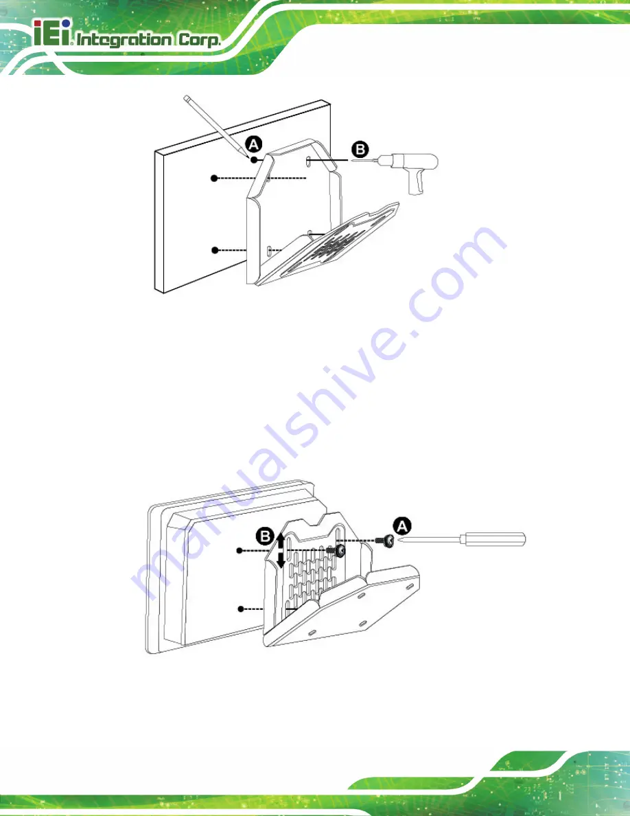
Step 2:
Align the screw holes on the V-Stand with the VESA mount screw holes on the
system rear panel.
Step 3:
Insert the four VESA mount screws into the four screw holes on the system rear
panel. Adjust the V-Stand to a proper position.
Step 4:
Tighten until the screw shank is secured against the rear panel.
Figure 3-23: Secure V-Stand to System
Содержание AFL3-W07A-BT-N1/PC/2G-R20
Страница 13: ...AFL3 W07A BT Panel PC Page 1 1 Introduction Chapter 1 ...
Страница 21: ...AFL3 W07A BT Panel PC Page 9 2 Unpacking Chapter 2 ...
Страница 25: ...AFL3 W07A BT Panel PC Page 13 3 Installation Chapter 3 ...
Страница 54: ...AFL3 W07A BT Panel PC Page 42 4 BIOS Setup Chapter 4 ...
Страница 82: ...AFL3 W07A BT Panel PC Page 70 5 System Maintenance Chapter 5 ...
Страница 88: ...AFL3 W07A BT Panel PC Page 76 6 Interface Connectors Chapter 6 ...
Страница 99: ...AFL3 W07A BT Panel PC Page 87 Appendix A A Regulatory Compliance ...
Страница 104: ...AFL3 W07A BT Panel PC Page 92 B Safety Precautions Appendix B ...
Страница 109: ...AFL3 W07A BT Panel PC Page 97 C BIOS Menu Options Appendix C ...
Страница 112: ...AFL3 W07A BT Panel PC Page 100 Appendix D D Watchdog Timer ...
Страница 115: ...AFL3 W07A BT Panel PC Page 103 E Hazardous Materials Disclosure Appendix E ...