AFL2-17A/AB-H61
P a g e 109
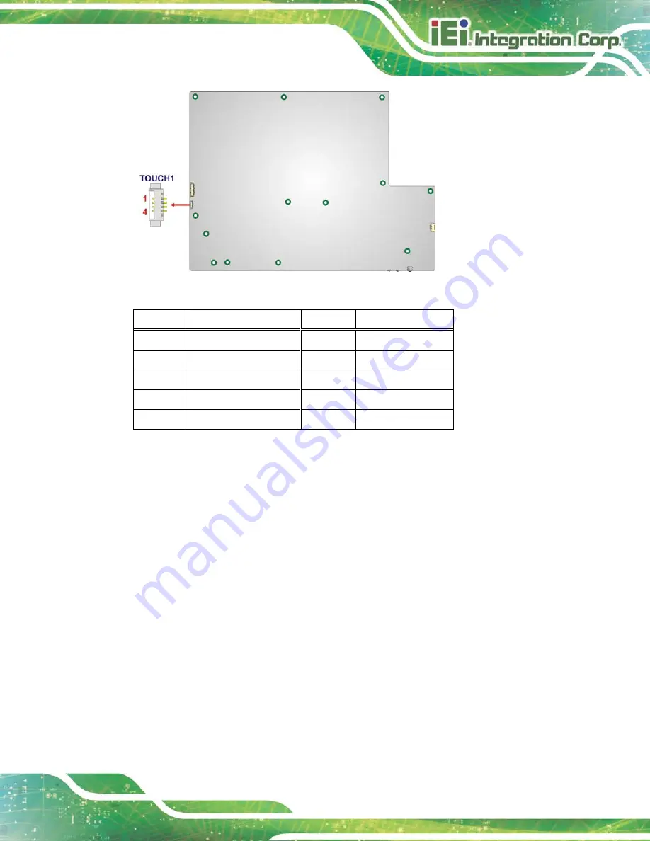
Figure 6-32: Touch Panel Connector Location
PIN NO.
DESCRIPTION
PIN NO.
DESCRIPTION
1
X+
2
X-
3
Y+
4
SENSE
5
X+
6
X-
7
Y+
8
Y-
9
GND
Table 6-28: Touch Panel Connector Pinouts
6.2.29
TP M Co n n e c to r
CN La b e l:
TP M1
CN Typ e :
20-pin header
CN Lo c a tio n :
See
CN P in o u ts :
See
The TPM connector connects to a TPM module.
Содержание AFL2-17A-H61 Series
Страница 21: ...AFL2 17A AB H61 Page 1 1 Introduction Chapter 1...
Страница 34: ...AFL2 17A AB H61 Page 14 2 LED Light Bar Optional Chapter 2...
Страница 57: ...AFL2 17A AB H61 Page 37 3 Detailed Specifications Chapter 3...
Страница 63: ...AFL2 17A AB H61 Page 43 4 Unpacking Chapter 4...
Страница 68: ...AFL2 17A AB H61 Page 48 5 Ins tallation Chapter 5...
Страница 98: ...AFL2 17A AB H61 Page 78 Chapter 6 6 Sys tem Motherboard...
Страница 134: ...AFL2 17A AB H61 Page 114 Figure 6 36 LCD panel Selection Jumper Location...
Страница 135: ...AFL2 17A AB H61 Page 115 7 Sys tem Maintenance Chapter 7...
Страница 144: ...AFL2 17A AB H61 Page 124 8 BIOS Setup Chapter 8...
Страница 181: ...AFL2 17A AB H61 Page 161 9 Software Drivers Chapter 9...
Страница 217: ...AFL2 17A AB H61 Panel PC Page 197 10 Cooling Management Cons ole iCMC Chapter 7...
Страница 226: ...AFL2 17A AB H61 Panel PC Page 206 A Safety Precautions Appendix A...
Страница 231: ...AFL2 17A AB H61 Panel PC Page 211 B BIOS Menu Options Appendix B...
Страница 234: ...AFL2 17A AB H61 Panel PC Page 214 Appendix C C One Key Recovery...
Страница 242: ...AFL2 17A AB H61 Panel PC Page 222 Figure C 5 Partition Creation Commands...
Страница 275: ...AFL2 17A AB H61 Panel PC Page 255 D Hazardous Materials Dis clos ure Appendix D...


