AFL-057A-Z510/Z530 Panel PC
Page 30
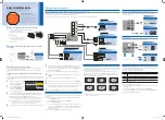
Figure 3-13: RJ-45 Connector with PoE Support
Step 2:
Connect the other end of the Cat 5 cable to a PoE-enabled networking device,
such as the IPS-2042TX Ethernet switch which can be purchased from IEI.
Figure 3-14: IPS-2042TX Ethernet Switch
Step 3:
Connect the PoE-enabled networking device to the power outlet.
Step 4:
The power LED on the front panel of the AFL-057A-Z510/Z530 will turn to green.
Содержание AFL-057A-Z510
Страница 12: ...AFL 057A Z510 Z530 Panel PC Page 1 Chapter 1 1 Introduction ...
Страница 20: ...AFL 057A Z510 Z530 Panel PC Page 9 Chapter 2 2 Packing List ...
Страница 25: ...AFL 057A Z510 Z530 Panel PC Page 14 Chapter 3 3 Installation ...
Страница 46: ...AFL 057A Z510 Z530 Panel PC Page 35 Chapter 4 4 System Maintenance ...
Страница 49: ...AFL 057A Z510 Z530 Panel PC Page 38 Figure 4 2 DDR2 SO DIMM Module Installation ...
Страница 50: ...AFL 057A Z510 Z530 Panel PC Page 39 Chapter 5 5 BIOS ...
Страница 76: ...AFL 057A Z510 Z530 Panel PC Page 65 Appendix A A Safety Precautions ...
Страница 81: ...AFL 057A Z510 Z530 Panel PC Page 70 Appendix B B BIOS Options ...
Страница 84: ...AFL 057A Z510 Z530 Panel PC Page 73 Appendix C C One Key Recovery ...
Страница 112: ...AFL 057A Z510 Z530 Panel PC Page 101 Appendix D D Terminology ...
Страница 116: ...AFL 057A Z510 Z530 Panel PC Page 105 Appendix E E Watchdog Timer ...
Страница 119: ...AFL 057A Z510 Z530 Panel PC Page 108 Appendix F F Hazardous Materials Disclosure ...


