Module 68
18 - 38
Operating instructions
IEF
-
Werner GmbH | Wendelhofstraße 6 | DE-78120 Furtwangen | www.ief-werner.de
Er
st
el
lt v
on
: F
ran
k R
ei
ch
el
t
|
MA
N
_E
N
_1040579_
Mo
d
ul
e 68_
R
2f
.d
oc
4.5
Wiring
4.5.1
Motors
NOTICE
The electrical connection of the motors is performed according to the motor data sheet.
For customer-specific motors, the data sheet must be requested from the respective manufacturer
and the motor connected accordingly.
4.5.2
Initiators
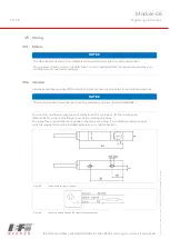
Inductive proximity switches (PNP normally closed) are used as standard stroke limitation switches.
NOTICE
The stroke limitation switches are not safety limitation switches according EN60204-1.
The initiators and their supply lines are protected in the carriage or, for the rotating unit
(Module 68 D), in the motor flange cover of the rotating unit drive.
The respective connections are centrally connected to one plug. If an additional reference point
switch is required, it must be installed externally in a suitable position.
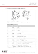
Figure 8
Dimension drawing of initiator
Figure 9
Connection designation PNP normally closed contact

