background image

Copyright © 2019, International Technologies & Systems Corp. All rights reserved. 

Page 9 of 24 


3.7


Operation LED


The Op-LED is a surface mount, tri-color LED, which is visible from the back of the housing (using 

a light pipe)

It is molded into the housing. The LED provides operating information for the PIN Pad. 

The following chart gives operation status meanings. The blink rate is about 12 times per minute 

with an LED-on period of about 2.5 second. 


LED State 

Operating Condition 

Off 

No power 

Steady Green 

Powered on, with keys injected, communication established 

Blinking Green 

Powered on, with Keys injected, no communication 

Steady Yellow 

Powered on, no keys, communication established 

Blinking Yellow 

Powered on, no keys, no communication established 

Steady Red 

Powered on & PIN pad is not functional 

Blinking Red 

Powered on, Tampering detected, keys erased 


3.8


Reliability


ESD: 

Passes 8kV contact and 8kV air discharge 


Drop Test: 

Withstands 3 ft drop to concrete, 6 surfaces & 4 corners, no functional damage 


MTBF: 

Minimum calculated MTBF value of 120,000 power on hours 


Key Stroke: 

The Key operational life is greater than 2,000,000 key stroke operations any one key. 


3.9


Peripheral Device Pairing


Unit has the ability to pair with other peripheral payment devices to complete MSR-Debit 

transactions 


3.10


Tamper Protection Features


The unit incorporates anti-tamper features, consisting of small buttons on the left and right edges of 

the housing (and two internal buttons, not accessible from the outside). When these buttons are 

depressed and the unit has been anti-tamper enabled via software commands (see 

Activate Fix 

Device

), any sudden release of tension on the buttons causes the unit to deactivate. (Also, 

cryptographic keys will be erased

.) Thus, unauthorized removal of the unit (theft, disassembly, etc.) 

will cause deactivation and make it impossible for sensitive data to be accessed or for the unit to be 

(re)used by an unauthorized user. 

Содержание SmartPIN K100 3.X

Страница 1: ... K100 3 X Technical Reference Manual 80114510 001 D July 3 2019 International Technologies Systems Corporation 10721 Walker Street Cypress CA 90630 4720 Tel 714 761 6368 Fax 714 761 8880 www idtechproducts com ...

Страница 2: ...New engineering drawings Miscellaneous edits Include USB VID PID Expanded explanation of Get Numeric Entry KT A 6 17 2016 Include tamper protection info Sections 3 10 6 4 6 5 KT B 6 22 2016 11 30 2016 Added USB descriptor info Removed sleep mode KT C 2 8 2017 2 14 2017 Add 75 46 28 Get All Key command Update 78 46 25 Get Key Status command KT D 7 3 2019 Added SRED Decommissioning text CB ...

Страница 3: ...ncluded in this warranty No person firm or corporation is authorized to assume for ID TECH any other liabilities in connection with the sales of any product In no event shall ID TECH be liable for any special incidental or consequential damages to purchaser or any third party caused by any defective item of equipment whether that defect is warranted against or not Purchaser s sole and exclusive re...

Страница 4: ... Interface Descriptor 11 4 1 4 HID Descriptor 11 4 1 5 End Point 1 Descriptor 11 4 1 6 End Point 2 Descriptor 11 4 1 7 Report Descriptor 12 5 0 COMMAND RESPONSE COMMUNICATIONS 12 6 0 PIN PAD TASK COMMANDS 12 6 1 GET ENCRYPTED PIN 12 6 2 GET NUMERIC ENTRY 13 6 3 GET FUNCTION KEY 14 6 4 GET ALL KEY 14 6 5 CANCEL COMMAND 14 6 6 BEEPER CONTROL 14 6 7 GET MODEL NUMBER 15 6 8 GET KEY STATUS 15 6 9 GET R...

Страница 5: ...ational Technologies Systems Corp All rights reserved Page 5 of 24 8 1 NOTE 20 8 2 SET BAUDRATE 20 8 3 GET BAUDRATE 20 8 4 SET PARITY 20 8 5 GET PARITY 20 8 6 SET STOPBITS 20 8 7 GET STOPBITS 21 9 0 ERROR CODES 22 NOTES 23 ...

Страница 6: ... to physical and electrical information this document presents firmware API specifications for communicating with the K100 via for example USB HID The low level firmware commands are applicable using either the USB HID or RS232 interface For RS232 interface the default COM parameters are 38400 8 1 none For USB the VID is 0xACD and the PID is 0x0850 2 0 Features PCI 3 X Certified 4x4 keypad layout ...

Страница 7: ... graphics are etched or engraved The operation keys CANC CLR ENT have engraved color bars near the bottom of the key surface The operation keys also have raised symbols X O Sequence from top to bottom CANCEL red CLEAR yellow ENTER green blank no color Faceplate Brushed finish stainless steel 3 2 Operating Environment Minimum Temperature Range Operating 40 to 80 C non condensing Non operating 40 to...

Страница 8: ...dback is available through a non oscillating beeper for keystrokes and operation alerts The beeper device provides a single pulse for audio feedback recognition of each key press The beeper can be given a time and frequency command to produce modulated tones The beeper is capable of producing a 75db sound level at 1 foot 3 6 Battery The battery provides power to maintain the contents of cryptograp...

Страница 9: ...y ESD Passes 8kV contact and 8kV air discharge Drop Test Withstands 3 ft drop to concrete 6 surfaces 4 corners no functional damage MTBF Minimum calculated MTBF value of 120 000 power on hours Key Stroke The Key operational life is greater than 2 000 000 key stroke operations any one key 3 9 Peripheral Device Pairing Unit has the ability to pair with other peripheral payment devices to complete MS...

Страница 10: ...y Microsoft In Linux you can run lsusb or usb devices from the shell to get device info Detailed USB HID descriptor information follows 4 1 1 Device Descriptor Field Value Description Length 12 Des type 01 bcd USB 00 02 USB2 0 Device Class 00 Unused Sub Class 00 Unused Device Protocol 00 Unused Max Packet Size 40 VID 0A CD PID 08 50 HID ID TECH StructureHID PINPAD BCD Device Release 00 02 i Manufa...

Страница 11: ...th 09 Des type 21 HID bcdHID 00 01 Control Code 00 numDescriptors 01 Number of Class Descriptors to follow DescriptorType 22 Report Descriptor Descriptor Length 1C 00 HID ID TECH format 4 1 5 End Point 1 Descriptor Field Value Description Length 07 Des type 05 End Point EP Addr 81 EP1 In Control Code 03 Interrupt MaxPacketSize 40 00 64 bytes bInterval 02 4 1 6 End Point 2 Descriptor Field Value De...

Страница 12: ...kLRC CheckSUM 03 Where Len_L Len_H is length of Command Body Response Body CheckLRC is LRC of Command Body Response Body exclusive OR of command body CheckSUM is SUM of Command Body Response Body 8 bit sum of command body If Command has an error the Response Body will be NAK with Error Code The Error Code can be found in a later section of this document 6 0 PIN Pad Task Commands 6 1 Get Encrypted ...

Страница 13: ...ng Encrypted PAN o If there is not BDK of Pairing MSR Key response 15 07 00 If there is BDK of Pairing MSR Key but not implement Pairing successfully response 15 07 01 If implemented Pairing successfully but the Encrypted PAN is error response is 15 07 02 If there is Internal Account from MSR according to there is PIN DUKPT Key or not the command is valid or response 15 04 00 15 07 00 No BDK of Pa...

Страница 14: ... K100 Sends 6 4 Get All Key Command Body is 75 46 28 This commands allows echoing any key Wait 3 Minutes While you press 0 9 key PIN pad Sends 0 9 While you press key PIN pad Sends While you press key PIN pad Sends While you press key PIN pad Sends While you press Back key PIN pad Sends B While you press Cancel key PIN pad Sends C While you press Enter key PIN pad Sends E 6 5 Cancel Command Comman...

Страница 15: ...is 06 If frequency is incorrect response is 15 6 7 Get Model Number Command Body is 75 46 0A Response Body is 06 IDPA 902000 RS232 Or Response Body is 06 IDPA 905000 USB HID 6 8 Get Key Status Command Body is 78 46 25 Response Body 06 Block Length KeyStatusBlock1 KeyStatusBlock2 KeyStatusBlockN Or 15 Error Code Where Block Length is 2 bytes format is Len_L Len_H is KeyStatusBlock Number KeyStatusB...

Страница 16: ...r is Number of Record Block If it is 0 there is no Record Block Record Block has the following format of UserID State 4 bytes Year 2 bytes Month 2 bytes Date 2 bytes Hour 2 bytes Minute Where o UserID is 0x31 User1 or 0x32 User2 o State is 0x30 Fix or 0x31 Removal o Year Month Date Hour and Minute need be ASCII code Note The Max Records is 20 After response this command all Records are deleted 6 1...

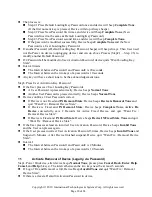
Страница 17: ...y and how to remove replace relocate the device for maintenance after anti tamper functionality has been enabled To activate anti tamper functionality once the unit is in place securely mounted with anti tamper buttons along the left and right edges of the housing depressed Step1 Power On device after device beeps Normal Tone please press Cancel Back Enter Help Back and Enter key 6 keys The interv...

Страница 18: ...rd is pressed correctly Device beeps Normal Tone Another User Password is pressed correctly Device beeps Normal Tone Device confirms 2 User Passwords correct If Device is not Fixed and IN Removal State Device beeps Device is Removal Tone and quit Want Fix Removal Device State If Device is Fixed and IN Removal State Device beeps Complete Tone Active Fix Device successfully save 2 Records for Active...

Страница 19: ...2 3 to modify another Default Password If 2 Password all be modified to User Activation Password device quit Want Loading Key State Interval The Interval between Password1 and Password2 is 2 Minutes The Interval between the two keys of a password is 10 Seconds Any key will have a short tone to be acknowledged tone Step3 Press User Activation Key Password If the User presses 2 User Loading Key Pass...

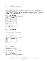
Страница 20: ... be valid when the device is connect with RS232 Cable 8 2 Set BaudRate Command Body is 70 53 01 41 01 ASCIIChar BaudRate ASCIIChar 2400 2 4800 3 9600 4 19200 6 38400 7 115200 9 Response Body is 06 8 3 Get BaudRate Command Body is 70 52 01 41 Response Body is 06 70 41 01 ASCIIChar 8 4 Set Parity Command Body is 70 53 01 43 01 ASCIIChar Parity ASCIIChar None 0 Odd 1 Even 2 Response Body is 06 8 5 Ge...

Страница 21: ... 2019 International Technologies Systems Corp All rights reserved Page 21 of 24 StopBits ASCIIChar 1 1 2 2 Response Body is 06 8 7 Get StopBits Command Body is 70 52 01 45 Response Body is 06 70 45 01 ASCIIChar ...

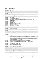
Страница 22: ...Press Cancel key after send Get Fun key Get Encrypted PIN Get Numeric 0x30FF Security Chip is not connect 0x3000 Only Security Chip is deactivation for No Secure data Unit is In Removal Legally State 0x3001 Only Security Chip is deactivation for ST Chip Firmware Check Error Unit is In Removal Legally State 0x3002 Only Security Chip is deactivation for Security Chip Firmware Check Error Unit is In ...

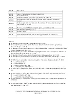
Страница 23: ...ctivation for ST Chip Firmware Check Error Unit is In Removal Legally State Response Body is 15 30 01 If Security Chip is de activation for Security Chip Firmware Check Error Unit is In Removal Legally State Response Body is 15 30 02 If Security Chip is de activation for Illegally Removal Response Body is 15 30 03 If Security Chip is activation Unit is In Removal Legally State Response Body is 15 ...

Страница 24: ...key Get Encrypted PIN Get Numeric Response Body is 15 18 00 If press Cancel key after send Get Fun key Get Encrypted PIN Get Numeric Response Body is 15 19 00 If device check keys sequence to enter Key Loading Status or Fix Removal Device Status response 15 74 00 for any tasks commands If Host receives this response please wait some seconds before sending command While any key is loading it should...

Отзывы: