4. DMA
115
PowerSpan II User Manual
80A1010_MA001_09
Integrated Device Technology
www.idt.com
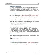
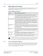
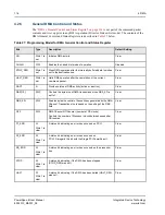
The starting byte address on the source port is specified in
“DMA x Source Address Register” on
. The starting byte address on the Destination port is specified in
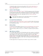
4.2.2
Transfer Control Register
“DMA x Transfer Control Register” on page 311
details the programming options for this register.
It controls the direction of the transfer, the endian conversion between the processor bus and the PCI
bus and specifies the transfer byte count. Note that the maximum byte count is 16 Mbytes. The DMA
Transfer Control Register is part of the command packet contents (
4.2.3
Command Packet Addressing
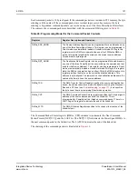
“DMA x Command Packet Pointer Register” on page 313
specifies the address for the command
packets in Linked-List mode. See
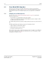
“Linked-List Mode DMA Operation” on page 120
for more details
on command packet processing.
4.2.4
Address Retry
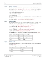
The Address Retry Enable (ARTRY_EN) bit in the
“Processor Bus Miscellaneous Control and Status
controls PowerSpan II’s assertion of PB_ARTRY_ during the servicing of
transactions. When the ARTRY_EN bit is set to 0, the PB Slave is disabled from generating address
retries.
4.2.4.1
DMA Addresses and Retries
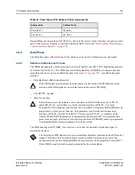
If a PowerSpan II DMA transaction is retried enough times the its retry counter may expire. When the
retry timer expires, the DMA transaction does not try to restart the transaction at the original address; it
jumps the address. The new address starts at the nearest address boundary. The nearest address
boundary depends on the value programmed in the DBS field (see
“DMA x General Control and Status
). For example, the nearest address boundary for an incremented address when
the DMA block size is set to 128 bytes is 0x80. In this case, the equation for the incremented address
value is: original a 0x80.
By advancing the address, PowerSpan II provides a method to step-out of the error condition.
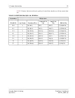
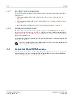
In the Single PCI PowerSpan II, the PCI-2 specific DMA bits must not be programmed.
DMA transfers must not be directed to the PCI-2 Interface.
Содержание PowerSpan II
Страница 8: ...Contents 8 PowerSpan II User Manual 80A1010_MA001_09 Integrated Device Technology www idt com ...
Страница 14: ...List of Tables 14 PowerSpan II User Manual 80A1010_MA001_09 Integrated Device Technology www idt com ...
Страница 18: ...About this Document 18 PowerSpan II User Manual 80A1010_MA001_09 Integrated Device Technology www idt com ...
Страница 82: ...2 PCI Interface 82 PowerSpan II User Manual 80A1010_MA001_09 Integrated Device Technology www idt com ...
Страница 112: ...3 Processor Bus Interface 112 PowerSpan II User Manual 80A1010_MA001_09 Integrated Device Technology www idt com ...
Страница 156: ...7 Interrupt Handling 156 PowerSpan II User Manual 80A1010_MA001_09 Integrated Device Technology www idt com ...
Страница 380: ...12 Register Descriptions 380 PowerSpan II User Manual 80A1010_MA001_09 Integrated Device Technology www idt com ...
Страница 394: ...14 Package Information 394 PowerSpan II User Manual 80A1010_MA001_09 Integrated Device Technology www idt com ...
Страница 414: ...15 AC Timing 414 PowerSpan II User Manual 80A1010_MA001_09 Integrated Device Technology www idt com ...
Страница 416: ...16 Ordering Information 416 PowerSpan II User Manual 80A1010_MA001_09 Integrated Device Technology www idt com ...
Страница 420: ...A Hardware Implementation 420 PowerSpan II User Manual 80A1010_MA001_09 Integrated Device Technology www idt com ...
Страница 428: ...B Typical Applications 428 PowerSpan II User Manual 80A1010_MA001_09 Integrated Device Technology www idt com ...
Страница 432: ...Glossary 432 PowerSpan II User Manual 80A1010_MA001_09 Integrated Device Technology www idt com ...

