IDT Switch Operation
Data Integrity
PES12N3 User Manual
4 - 4
June 7, 2006
Notes
Data Integrity
PCI Express® provides reliable hop-by-hop communication between interconnected devices, such as
roots, switches, and endpoints, by utilizing a 32-bit Link CRC (LCRC), sequence numbers, and a link level
retransmission protocol. While this mechanism provides reliable communication between interconnected
devices, it does not protect against corruption that may occur inside of a device. PCI Express defines an
optional end-to-end data integrity mechanism that consists of appending a 32-bit end-to-end CRC (ECRC)
computed at the source over the invariant fields of a Transaction Layer Packet (TLP) that is checked at the
ultimate destination of the TLP. While this mechanism provides end-to-end error detection, unfortunately it
is an optional PCI Express feature and has not been implemented in some North bridges and endpoints. In
addition, the ECRC mechanism does not cover variant fields within a TLP.
Since deep sub-micron devices are known to be susceptible to single-event-upsets, a mechanism is
desired that detects errors that occur within a PCI express switch. The PES12N3 parity protects all TLPs in
the switch, thus enabling corruption that may occur inside of the device to be detected and reported even in
systems that do not implement ECRC.
1
Associated with each port of the PES12N3 is a PCI-PCI bridge. Located in the switch integrity region in
extended configuration space of each PCI-PCI bridge are the Switch System Integrity Control (SWSICTL)
and Switch System Integrity Parity Error Count (SWSIPECNT) registers. These registers provide control
and status over switch errors associated with that switch port and may be read by a root or via the slave
SMBus interface.
Data flowing into the PES12N3 is protected by the LCRC. Within the Data Link (DL) layer of the switch
ingress port, the LCRC is checked and 32-bit Doubleword (DWord) even parity is computed on the received
TLP data. If an LCRC error is detected at this point, the link level retransmission protocol is used to recover
from the error by forcing a retransmission by the link partner. As the TLP flows through the switch, its align-
ment or contents may be modified. In all such cases, parity is updated and not recomputed. Hence, any
error that occurs is propagated and not masked by a parity regeneration. When the TLP reaches the DL
layer of the switch egress port, parity is checked and in parallel a LCRC is computed. If the TLP is parity
error free, then the LCRC and TLP contents are known to be correct and the LCRC is used to protect the
packet through the lower portion of the DL layer, PHY layer, and link transmission.
If a parity error is detected by the DL layer of an egress port, then the TLP is nullified by inverting the
computed LCRC and ending the packet with an EDB symbol. Nullified TLPs received by the link-partner are
discarded. In addition to nullifying the TLP, the PES12N3 performs the following when a parity error is
detected: sends an error non-fatal (ERR_NONFATAL) message (if this message reporting is enabled) to the
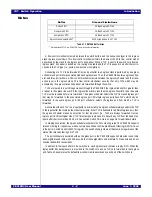
Routing Method
TLP Type Using Routing Method
Route by Address
MRd, MrdLk, MWr, IORd, IOWr, Msg, MsgD
ID Based Routing
CfgRd0, CfgWr0, CfgRd1, CfgWr1, Cpl, CpdD, CplLk, CplDLk,
Msg, MsgD
Imlicit Routing - Route to Root
Msg, MsgD
Implicit Routing - Broadcast from Root
1
1.
Broadcast from root messages are only accepted from the root port (i.e., port A). An unsupported request is generated
if a TLP with this routing method is received from any other port.
Msg, MsgD
Implicit Routing - Local
Msg, MsgD
Implicit Routing - Gathered and Routed to
Root
Only supported for PME_TO_Ack messages in response to a
root initiated PME_Turn_Off message.
Table 4.3 Switch Routing Methods
1.
Nullified TLPs are not parity protected and no parity errors are reported for nullified TLPs since these TLPs are
discarded.
Содержание 89HPES12N3
Страница 10: ...IDT Table of Contents PES12N3 User Manual iv June 7 2006 Notes...
Страница 14: ...IDT List of Figures PES12N3 User Manual viii June 7 2006 Notes...
Страница 36: ...IDT Clocking Reset and Initialization Reset PES12N3 User Manual 2 8 June 7 2006 Notes...
Страница 40: ...IDT Link Operation Slot Power Limit Support PES12N3 User Manual 3 4 June 7 2006 Notes...
Страница 50: ...IDT Switch Operation Switch Core Errors PES12N3 User Manual 4 10 June 7 2006 Notes...
Страница 54: ...IDT Power Management Active State Power Management PES12N3 User Manual 5 4 June 7 2006 Notes...
Страница 62: ...IDT Hot Plug and Hot Swap Hot Swap PES12N3 User Manual 6 8 June 7 2006 Notes...
Страница 78: ...IDT SMBus Interfaces Slave SMBus Interface PES12N3 User Manual 7 16 June 7 2006 Notes...
Страница 142: ...IDT Transparent Mode Operation Generic PCI to PCI Bridge Register Definition PES12N3 User Manual 9 62 June 7 2006 Notes...
Страница 148: ...IDT Test and Debug SerDes Test Clock PES12N3 User Manual 10 6 June 7 2006...
Страница 158: ...IDT JTAG Boundary Scan Usage Considerations PES12N3 User Manual 11 10 June 7 2006 Notes...


