


27: F
LOW
C
ALCULATION
I
NSTRUCTIONS
27-18
FC6A S
ERIES
MICROS
MART
L
ADDER
P
ROGRAMMING
M
ANUAL
FC9Y-B1726
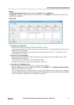
FLWP (Pulse Flow Totalizer)
This instruction monitors a counter that measures the number of pulses and calculates the flow rate at a fixed cycle. It also stores
the accumulated flow volume (the amount that flowed for an arbitrary period) to a log.
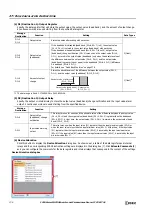
Symbol
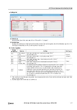
Operation
The FLWP instruction calculates the flow rate and the accumulated flow volume by acquiring the pulse signal output from a pulse
output type flow meter using a counter and monitoring the value of that counter. That result is stored in the devices specified by
D1 (status) and D2 (logged data).
The FLWP instruction has a flow rate calculation function that calculates the flow rate from pulses, a totalizer function that
accumulates the flow volume, and a log output function to temporarily save the accumulated volume at the desired time.
Note:
When using an analog output type flow meter, the FLWA instruction can be used to monitor the flow volume. For details on the FLWA
instruction, see "FLWA (Analog Flow Totalizer)" on page 27-9.
Notes:
• The maximum frequency of pulses that the FLWP instruction supports is 10 kHz.
• Output the log in a cycle within 119 hours.
• The FLWP instruction cannot be used in an interrupt program. If used in an interrupt program, a user program execution error occurs, the
execution of the instruction is canceled, and the next instruction is executed.
For user program execution errors, see "User Program Execution Errors" on page 3-10.
• The FLWP instruction must be executed with each scan as set or it cannot correctly measure the time. Therefore, it cannot be simultaneously
used with the LABEL, LJMP, LCAL, LRET, JMP, JEND, MCS, and MCR instructions.
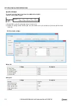
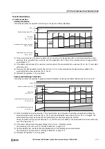
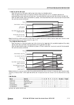
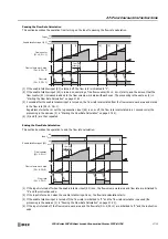
Flow Rate Calculation Function Overview
When the input is on, if the enable totalizer input (S2) is turned on, the amount that the flow counter (S1+0, S1+1)
increased is added to the flow volume work area with each scan. The flow rate (D1+0, D1+1) is updated every second with
the result that is calculated from the flow volume work area.
If the enable totalizer input is turned off, the flow rate is initialized to "0" and updating the flow rate is stopped.
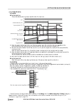
Note:
For details on the flow calculation function such as the operation immediately after the input is turned on and the operation when the enable
totalizer input is once again turned on, see "Flow Rate Function" on page 27-20.
D1
*****
S2
*****
FLWP(*)
S1
*****
S3
*****
D2
*****
Enable totalizer input (S2)
Input
ON
OFF
Flow counter
(S1+0, S1+1)
ON
OFF
1 s
Flow volume work area
(D1+8, D1+9)
Flow rate
(D1+0, D1+1)
Flow rate
update cycle
Flow rate
update cycle
Flow rate
update cycle
Содержание MICROSmart FC6A Series
Страница 1: ...B 1726 7 FC6A SERIES Ladder Programming Manual ...
Страница 8: ...Preface 7 FC6A SERIES MICROSMART LADDER PROGRAMMING MANUAL FC9Y B1726 ...
Страница 32: ...1 OPERATION BASICS 1 20 FC6A SERIES MICROSMART LADDER PROGRAMMING MANUAL FC9Y B1726 ...
Страница 96: ...3 INSTRUCTIONS REFERENCE 3 18 FC6A SERIES MICROSMART LADDER PROGRAMMING MANUAL FC9Y B1726 ...
Страница 130: ...4 BASIC INSTRUCTIONS 4 34 FC6A SERIES MICROSMART LADDER PROGRAMMING MANUAL FC9Y B1726 ...
Страница 158: ...6 DATA COMPARISON INSTRUCTIONS 6 10 FC6A SERIES MICROSMART LADDER PROGRAMMING MANUAL FC9Y B1726 ...
Страница 192: ...9 SHIFT ROTATE INSTRUCTIONS 9 12 FC6A SERIES MICROSMART LADDER PROGRAMMING MANUAL FC9Y B1726 ...
Страница 216: ...10 DATA CONVERSION INSTRUCTIONS 10 24 FC6A SERIES MICROSMART LADDER PROGRAMMING MANUAL FC9Y B1726 ...
Страница 248: ...11 WEEK PROGRAMMER INSTRUCTIONS 11 32 FC6A SERIES MICROSMART LADDER PROGRAMMING MANUAL FC9Y B1726 ...
Страница 272: ...12 DISPLAY INSTRUCTIONS 12 24 FC6A SERIES MICROSMART LADDER PROGRAMMING MANUAL FC9Y B1726 ...
Страница 284: ...14 REFRESH INSTRUCTIONS 14 6 FC6A SERIES MICROSMART LADDER PROGRAMMING MANUAL FC9Y B1726 ...
Страница 288: ...15 INTERRUPT CONTROL INSTRUCTIONS 15 4 FC6A SERIES MICROSMART LADDER PROGRAMMING MANUAL FC9Y B1726 ...
Страница 294: ...16 COORDINATE CONVERSION INSTRUCTIONS 16 6 FC6A SERIES MICROSMART LADDER PROGRAMMING MANUAL FC9Y B1726 ...
Страница 374: ...18 PULSE OUTPUT INSTRUCTIONS 18 78 FC6A SERIES MICROSMART LADDER PROGRAMMING MANUAL FC9Y B1726 Setting ...
Страница 450: ...20 DUAL TEACHING TIMER INSTRUCTIONS 20 4 FC6A SERIES MICROSMART LADDER PROGRAMMING MANUAL FC9Y B1726 ...
Страница 502: ...25 DATA LOG INSTRUCTIONS 25 22 FC6A SERIES MICROSMART LADDER PROGRAMMING MANUAL FC9Y B1726 ...
Страница 546: ...26 SCRIPT 26 44 FC6A SERIES MICROSMART LADDER PROGRAMMING MANUAL FC9Y B1726 ...
Страница 574: ...27 FLOW CALCULATION INSTRUCTIONS 27 28 FC6A SERIES MICROSMART LADDER PROGRAMMING MANUAL FC9Y B1726 ...
Страница 583: ...FC6A SERIES MICROSMART LADDER PROGRAMMING MANUAL FC9Y B1726 28 9 28 USER DEFINED MACRO INSTRUCTION ...
Страница 584: ...28 USER DEFINED MACRO INSTRUCTION 28 10 FC6A SERIES MICROSMART LADDER PROGRAMMING MANUAL FC9Y B1726 ...
Страница 598: ...APPENDIX A 14 FC6A SERIES MICROSMART LADDER PROGRAMMING MANUAL FC9Y B1726 ...


