


22: L
OGARITHM
/ P
OWER
I
NSTRUCTIONS
22-4
FC6A S
ERIES
MICROS
MART
L
ADDER
P
ROGRAMMING
M
ANUAL
FC9Y-B1726
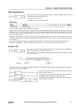
POW (Power)
Valid Devices
For valid device address ranges, see "Device Addresses" on page 2-1.
When the operation result is not within the range between –3.402823
×
10
38
and –1.175495
×
10
–38
or between 1.175495
×
10
–38
to
3.402823
×
10
38
, special internal relay M8003 (carry or borrow) is turned on, except when the result is 0. For details, see "Carry and Borrow in
Floating-Point Data Processing" on page 3-8.
When the operation result is between –1.175495
×
10
–38
and 1.175495
×
10
–38
, the destination device designated by D1 stores 0. When the
operation result is less than –3.402823
×
10
38
or greater than 3.402823
×
10
38
, causing an overflow, the destination device designated by D1 stores
a value of minus or plus infinity.
When one of the following conditions occurs, a user program execution error occurs.
• The data designated by source device S1 is less than 0 and the data designated by source device S2 is not an integer.
• The data designated by source device S1 is 0 and the data designated by source device S2 is less than or equal to 0.
When the data designated by source device S1 or S2 does not comply with the normal floating-point format, a user program execution error occurs,
and the execution of the instruction is canceled. The value of D1 is left unchanged and the next instruction is executed.
When a user program execution error occurs, special internal relay M8004 and ERR LED on the FC6A Series MICROSmart are turned on. For details
about the user program execution errors, see "User Program Execution Errors" on page 3-10.
Since the POW instruction is executed in each scan while input is on, a pulse input from a SOTU or SOTD instruction should be used.
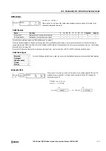
Valid Data Types
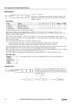
Example: POW
S1·S1+1
S2·S2+1
→
D1·D1+1
When input is on, data assigned by source device S1 is raised to the power S2·S2+1
assigned by source device S2 and the operation result is stored to the destination
assigned by device D1.
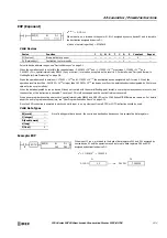
POW(F)
S1
*****
D1
*****
S2
*****
Device
Function
I
Q
M
R
T
C
D
P
Constant
Repeat
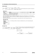
S1 (Source 1)
Binary data of base
—
—
—
—
—
—
X
—
X
—
S2 (Source 2)
Binary data of exponent
—
—
—
—
—
—
X
—
X
—
D1 (Destination 1)
Destination to store results
—
—
—
—
—
—
X
—
—
—
W (word)
—
Since floating point data is used, the source and destination devices use two consecutive data registers.
I (integer)
—
D (double word)
—
L (long)
—
F (float)
X
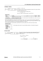
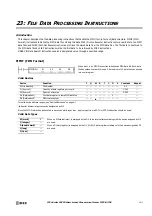
When input I1 is on, the data of data registers D10 and D11 assigned by
source device S1 is raised to the power D20·D20+1 assigned by source device
S2 and the operation result is stored to data registers D30 and D31 assigned
by destination device D1.
I1
S2
D20
POW(F)
D1
D30
SOTU
S1
D10
4
1.25
→
5.656854
S2
S1
4.0
D10·D11
1.25
D20·D21
D1
5.656854
D30·D31
Содержание MICROSmart FC6A Series
Страница 1: ...B 1726 7 FC6A SERIES Ladder Programming Manual ...
Страница 8: ...Preface 7 FC6A SERIES MICROSMART LADDER PROGRAMMING MANUAL FC9Y B1726 ...
Страница 32: ...1 OPERATION BASICS 1 20 FC6A SERIES MICROSMART LADDER PROGRAMMING MANUAL FC9Y B1726 ...
Страница 96: ...3 INSTRUCTIONS REFERENCE 3 18 FC6A SERIES MICROSMART LADDER PROGRAMMING MANUAL FC9Y B1726 ...
Страница 130: ...4 BASIC INSTRUCTIONS 4 34 FC6A SERIES MICROSMART LADDER PROGRAMMING MANUAL FC9Y B1726 ...
Страница 158: ...6 DATA COMPARISON INSTRUCTIONS 6 10 FC6A SERIES MICROSMART LADDER PROGRAMMING MANUAL FC9Y B1726 ...
Страница 192: ...9 SHIFT ROTATE INSTRUCTIONS 9 12 FC6A SERIES MICROSMART LADDER PROGRAMMING MANUAL FC9Y B1726 ...
Страница 216: ...10 DATA CONVERSION INSTRUCTIONS 10 24 FC6A SERIES MICROSMART LADDER PROGRAMMING MANUAL FC9Y B1726 ...
Страница 248: ...11 WEEK PROGRAMMER INSTRUCTIONS 11 32 FC6A SERIES MICROSMART LADDER PROGRAMMING MANUAL FC9Y B1726 ...
Страница 272: ...12 DISPLAY INSTRUCTIONS 12 24 FC6A SERIES MICROSMART LADDER PROGRAMMING MANUAL FC9Y B1726 ...
Страница 284: ...14 REFRESH INSTRUCTIONS 14 6 FC6A SERIES MICROSMART LADDER PROGRAMMING MANUAL FC9Y B1726 ...
Страница 288: ...15 INTERRUPT CONTROL INSTRUCTIONS 15 4 FC6A SERIES MICROSMART LADDER PROGRAMMING MANUAL FC9Y B1726 ...
Страница 294: ...16 COORDINATE CONVERSION INSTRUCTIONS 16 6 FC6A SERIES MICROSMART LADDER PROGRAMMING MANUAL FC9Y B1726 ...
Страница 374: ...18 PULSE OUTPUT INSTRUCTIONS 18 78 FC6A SERIES MICROSMART LADDER PROGRAMMING MANUAL FC9Y B1726 Setting ...
Страница 450: ...20 DUAL TEACHING TIMER INSTRUCTIONS 20 4 FC6A SERIES MICROSMART LADDER PROGRAMMING MANUAL FC9Y B1726 ...
Страница 502: ...25 DATA LOG INSTRUCTIONS 25 22 FC6A SERIES MICROSMART LADDER PROGRAMMING MANUAL FC9Y B1726 ...
Страница 546: ...26 SCRIPT 26 44 FC6A SERIES MICROSMART LADDER PROGRAMMING MANUAL FC9Y B1726 ...
Страница 574: ...27 FLOW CALCULATION INSTRUCTIONS 27 28 FC6A SERIES MICROSMART LADDER PROGRAMMING MANUAL FC9Y B1726 ...
Страница 583: ...FC6A SERIES MICROSMART LADDER PROGRAMMING MANUAL FC9Y B1726 28 9 28 USER DEFINED MACRO INSTRUCTION ...
Страница 584: ...28 USER DEFINED MACRO INSTRUCTION 28 10 FC6A SERIES MICROSMART LADDER PROGRAMMING MANUAL FC9Y B1726 ...
Страница 598: ...APPENDIX A 14 FC6A SERIES MICROSMART LADDER PROGRAMMING MANUAL FC9Y B1726 ...


