


21:
C
OMPUTER
L
INK
C
OMMUNICATION
FC5A
M
ICRO
S
MART
U
SER
’
S
M
ANUAL
FC9Y
‐
B1273
21
‐
3
Assigning
Network
Numbers
When
assigning
a
unique
network
number
of
0
through
31
to
each
CPU
module
for
the
1:N
computer
link
network,
download
the
user
program
containing
the
network
number
setting
to
each
CPU
module
in
the
1:1
computer
link
system,
then
the
new
network
number
is
assigned
to
the
CPU
module.
Make
sure
that
there
is
no
duplication
of
network
num
‐
bers
in
a
1:N
computer
link
network.
Communication
Settings
When
monitoring
the
MicroSmart
operation
or
downloading
a
user
program
using
WindLDR
,
make
sure
that
the
same
communication
settings
are
selected
for
the
CPU
module
and
WindLDR
,
so
that
the
computer
communicates
with
the
MicroSmart
in
either
the
1:1
or
1:N
computer
link
system.
To
change
the
communication
settings
for
WindLDR
,
access
the
Communication
Settings
dialog
box
from
the
Configure
menu
as
shown
below.
When
communicating
in
the
1:N
computer
link
system
for
monitoring
or
downloading,
select
the
network
number
of
the
CPU
module
also
in
the
Communication
Settings
dialog
box.
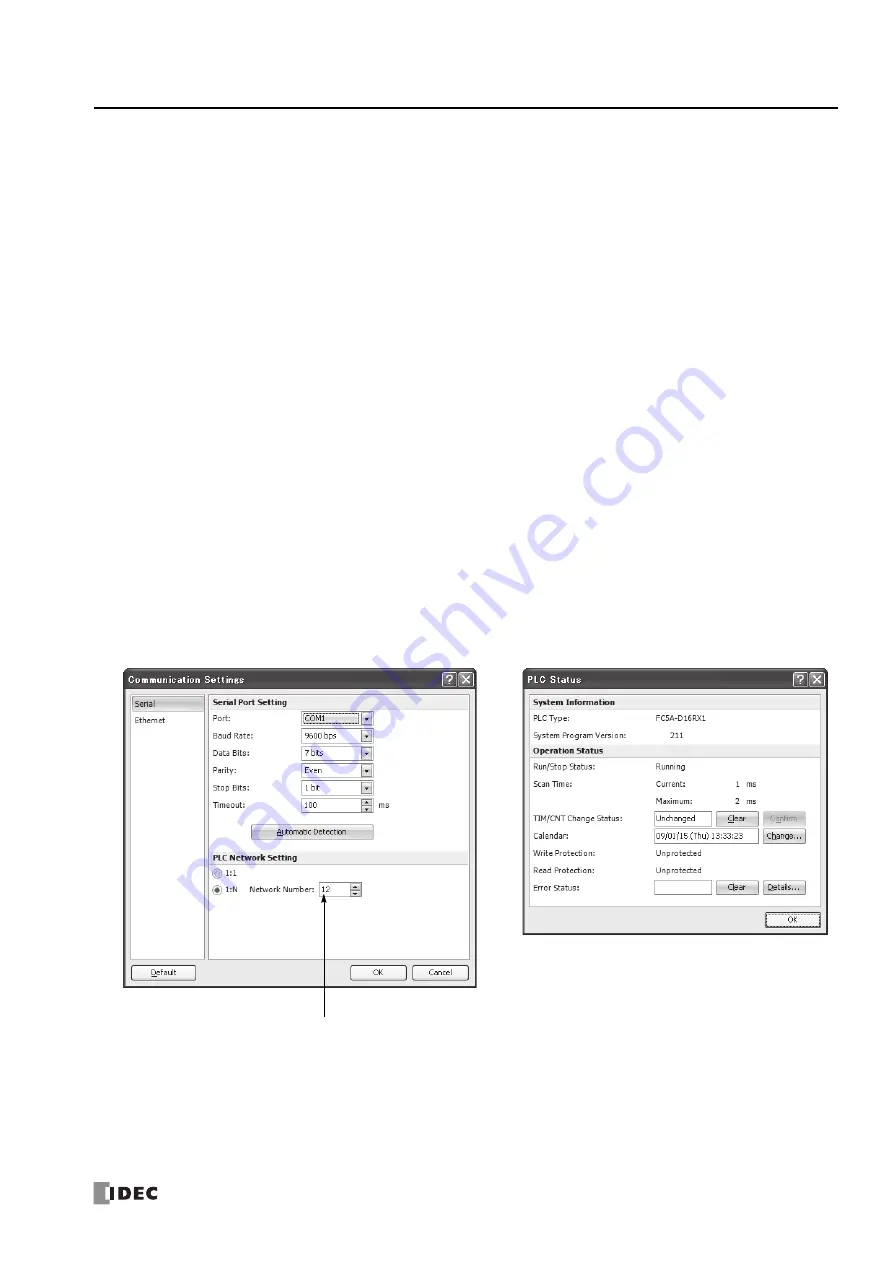
Monitoring
PLC
Status
The
following
example
describes
the
procedures
to
monitor
the
operating
status
of
the
MicroSmart
assigned
with
net
‐
work
number
12
in
a
1:N
communication
computer
link
system.
1.
From
the
WindLDR
menu
bar,
select
Online
>
Set
Up
.
The
Communication
Settings
dialog
box
appears.
2.
Under
PLC
Network
Setting,
click
the
1:N
button
to
select
1:N
communication,
and
select
12
in
the
Network
Number
field.
3.
From
the
WindLDR
menu
bar,
select
Online
>
Monitor
>
Monitor
.
The
ladder
diagram
on
the
screen
enters
the
monitor
mode.
4.
From
the
WindLDR
menu
bar,
select
Online
>
Status
.
The
PLC
Status
dialog
box
appears.
Network
Number:
Enter
12
to
select
a
network
num
‐
ber
to
communicate
with.
Содержание MICROSmart FC5A Series
Страница 1: ...FC5A SERIES FC9Y B1273 1 User s Manual Advanced Volume ...
Страница 2: ......
Страница 8: ...Preface 6 FC5A MicroSmart User s Manual FC9Y B1273 ...
Страница 14: ...TABLE OF CONTENTS vi FC5A MICROSMART USER S MANUAL FC9Y B1273 ...
Страница 52: ...4 DATA COMPARISON INSTRUCTIONS 4 10 FC5A MICROSMART USER S MANUAL FC9Y B1273 ...
Страница 72: ...5 Binary Arithmetic Instructions 5 20 FC5A MicroSmart User s Manual FC9Y B1273 ...
Страница 88: ...7 SHIFT ROTATE INSTRUCTIONS 7 12 FC5A MicroSmart User s Manual FC9Y B1273 ...
Страница 112: ...8 DATA CONVERSION INSTRUCTIONS 8 24 FC5A MicroSmart User s Manual FC9Y B1273 ...
Страница 138: ...11 PROGRAM BRANCHING INSTRUCTIONS 11 14 FC5A MICROSMART USER S MANUAL FC9Y B1273 ...
Страница 178: ...13 PULSE INSTRUCTIONS 13 32 FC5A MICROSMART USER S MANUAL FC9Y B1273 ...
Страница 202: ...14 PID INSTRUCTION 14 24 FC5A MICROSMART USER S MANUAL FC9Y B1273 ...
Страница 206: ...15 DUAL TEACHING TIMER INSTRUCTIONS 15 4 FC5A MICROSMART USER S MANUAL FC9Y B1273 ...
Страница 214: ...16 INTELLIGENT MODULE ACCESS INSTRUCTIONS 16 8 FC5A MICROSMART USER S MANUAL FC9Y B1273 ...
Страница 248: ...21 COMPUTER LINK COMMUNICATION 21 4 FC5A MICROSMART USER S MANUAL FC9Y B1273 ...
Страница 272: ...23 MODBUS TCP COMMUNICATION 23 10 FC5A MICROSMART USER S MANUAL FC9Y B1273 ...
Страница 332: ...25 EXPANSION RS232C RS485 COMMUNICATION 25 16 FC5A MICROSMART USER S MANUAL FC9Y B1273 ...
Страница 341: ...NOTE FC5A MICROSMART USER S MANUAL FC9Y B1273 1 ...
Страница 342: ...NOTE 2 FC5A MICROSMART USER S MANUAL FC9Y B1273 ...


