


14:
PID
I
NSTRUCTION
FC5A
M
ICRO
S
MART
U
SER
’
S
M
ANUAL
FC9Y
‐
B1273
14
‐
17
While
manual
mode
is
enabled
with
the
auto/manual
mode
control
relay
(S2+1)
set
to
on,
S1+1
stores
0
through
100
of
the
manual
mode
output
manipulated
variable
(S1+18),
and
D1
stores
an
indefinite
value
irrespective
of
the
S1+18
value.
While
auto
tuning
is
in
progress,
S1+1
stores
0
through
100
of
the
AT
output
manipulated
variable
(S1+22),
and
D1
stores
an
indefinite
value.
While
advanced
auto
tuning
is
in
progress,
S1+1
and
D1
store
an
indefinite
value.
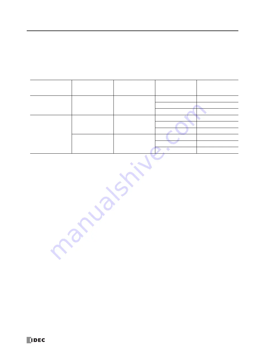
Examples
of
Output
Manipulated
Variable
Values
IMPORTANT
The
control
output
(S2+6)
is
turned
on
and
off
according
to
the
control
period
(S1+13)
and
the
output
manipulated
vari
‐
able
(S1+1).
When
an
feedback
system
consists
of
the
control
output
(S2+6),
optimum
control
may
not
be
achieved
for
some
controlled
object,
then
it
is
recommended
that
a
feedback
control
system
be
programmed
using
the
calculation
results
of
the
manipulated
variable
(D1).
Notes
for
Using
the
PID
Instruction:
Since
the
PID
instruction
requires
continuous
operation,
keep
on
the
start
input
for
the
PID
instruction.
The
high
alarm
output
(S2+4)
and
the
low
alarm
output
(S2+5)
work
while
the
start
input
for
the
PID
instruction
is
on.
These
alarm
outputs,
however,
do
not
work
when
a
PID
instruction
execution
error
occurs
(S1+2
stores
100
or
more)
due
to
data
error
in
control
data
registers
S1+0
through
S1+26
or
while
the
start
input
for
the
PID
instruction
is
off.
Provide
a
program
to
monitor
the
process
variable
(S4)
separately.
When
a
PID
execution
error
occurs
(S1+2
stores
100
or
more)
or
when
auto
tuning
is
completed,
the
manipulated
variable
(D1)
stores
0
and
the
control
output
(S2+6)
turns
off.
Do
not
use
the
PID
instruction
in
program
branching
instructions:
LABEL,
LJMP,
LCAL,
LRET,
JMP,
JEND,
MCS,
and
MCR.
The
PID
instruction
may
not
operate
correctly
in
these
instructions.
The
PID
instruction,
using
the
difference
between
the
set
point
(S3)
and
process
variable
(S4)
as
input,
calculates
the
manipulated
variable
(D1)
according
to
the
PID
parameters,
such
as
proportional
term
(S1+7),
integral
time
(S1+8),
and
derivative
time
(S1+9).
When
the
set
point
(S3)
or
process
variable
(S4)
is
changed
due
to
disturbance,
overshoot
or
undershoot
will
be
caused.
Before
put
‐
ting
the
PID
control
into
actual
application,
perform
simulation
tests
by
changing
the
set
point
and
process
variable
(disturbance)
to
anticipated
values
in
the
application.
The
PID
parameters,
such
as
proportional
term
(S1+7),
integral
time
(S1+8),
and
derivative
time
(S1+9),
determined
by
the
auto
tun
‐
ing
may
not
always
be
the
optimum
values
depending
on
the
actual
application.
To
make
sure
of
the
best
results,
adjust
the
parame
‐
ters.
Once
the
best
PID
parameters
are
determined,
perform
only
the
PID
action
in
usual
operation
unless
the
control
object
is
changed.
Output
Manipulated
Variable
Limit
Enable
(S2+2)
Output
Manipulated
Variable
Upper
Limit
(S1+16)
Output
Manipulated
Variable
Lower
Limit
(S1+17)
Manipulated
Variable
(D1)
Output
Manipulated
Variable
(S1+1)
OFF
(disabled)
—
—
100
100
1
to
99
1
to
99
0
0
ON
(enabled)
50
25
50
50
26
to
49
26
to
49
25
25
10050
—
100
50
1
to
99
(1
to
99)
0.5
0
0
Содержание MICROSmart FC5A Series
Страница 1: ...FC5A SERIES FC9Y B1273 1 User s Manual Advanced Volume ...
Страница 2: ......
Страница 8: ...Preface 6 FC5A MicroSmart User s Manual FC9Y B1273 ...
Страница 14: ...TABLE OF CONTENTS vi FC5A MICROSMART USER S MANUAL FC9Y B1273 ...
Страница 52: ...4 DATA COMPARISON INSTRUCTIONS 4 10 FC5A MICROSMART USER S MANUAL FC9Y B1273 ...
Страница 72: ...5 Binary Arithmetic Instructions 5 20 FC5A MicroSmart User s Manual FC9Y B1273 ...
Страница 88: ...7 SHIFT ROTATE INSTRUCTIONS 7 12 FC5A MicroSmart User s Manual FC9Y B1273 ...
Страница 112: ...8 DATA CONVERSION INSTRUCTIONS 8 24 FC5A MicroSmart User s Manual FC9Y B1273 ...
Страница 138: ...11 PROGRAM BRANCHING INSTRUCTIONS 11 14 FC5A MICROSMART USER S MANUAL FC9Y B1273 ...
Страница 178: ...13 PULSE INSTRUCTIONS 13 32 FC5A MICROSMART USER S MANUAL FC9Y B1273 ...
Страница 202: ...14 PID INSTRUCTION 14 24 FC5A MICROSMART USER S MANUAL FC9Y B1273 ...
Страница 206: ...15 DUAL TEACHING TIMER INSTRUCTIONS 15 4 FC5A MICROSMART USER S MANUAL FC9Y B1273 ...
Страница 214: ...16 INTELLIGENT MODULE ACCESS INSTRUCTIONS 16 8 FC5A MICROSMART USER S MANUAL FC9Y B1273 ...
Страница 248: ...21 COMPUTER LINK COMMUNICATION 21 4 FC5A MICROSMART USER S MANUAL FC9Y B1273 ...
Страница 272: ...23 MODBUS TCP COMMUNICATION 23 10 FC5A MICROSMART USER S MANUAL FC9Y B1273 ...
Страница 332: ...25 EXPANSION RS232C RS485 COMMUNICATION 25 16 FC5A MICROSMART USER S MANUAL FC9Y B1273 ...
Страница 341: ...NOTE FC5A MICROSMART USER S MANUAL FC9Y B1273 1 ...
Страница 342: ...NOTE 2 FC5A MICROSMART USER S MANUAL FC9Y B1273 ...


