


SERVICE AND TECHNICAL SUPPORT MANUAL
Gas Furnace: F9MES
Specifications subject to change without notice.
12
440 04 4900 02
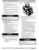
Checklist
1. Put away tools and instruments. Clean up debris.
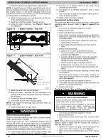
2. Verify that the jumper is removed from the TEST/TWIN
terminal. Verify that there is nothing plugged into the PLT
connector.
NOTE
: If there is a jumper connector plugged into PLT, remove
it and discard. (See
3. Verify that the Blower/Heat Off Delay jumpers are set as
desired. (See
and
4. Verify that the blower (lower door in upflow position) and
control (“Main” or upper door in upflow position) doors
are properly installed.
5. Verify that the Status LED has heartbeat (bright
−
dim). If
not, check that the power supply is energized and that
the blower door is secure. See
to interpret
diagnostic codes
.
6. Cycle test furnace with room thermostat to be sure that it
operates properly with the room thermostat. Check all
modes including Heat, Cool and Fan.
7. Check operation of accessories per manufacturer’s
instructions.
8. Review Home Owner’s Information with owner.
9. Attach entire literature packet to furnace.
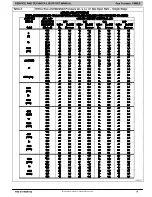
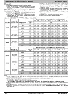
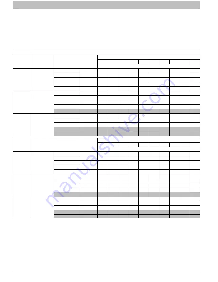
Table 5
COOLING AIR DELIVERY - CFM and L/s (with filter
1
)
UNIT SIZE
RETURN-AIR-
CONNECTION
WIRE COLOR
COOLING
TONS
AIRFLOW DELIVERY @ EXTERNAL STATIC PRESSURE (in. w.c.)
0.1
0.2
0.3
0.4
0.5
0.6
0.7
0.8
0.9
1.0
CFM
1002120
BOTTOM or
TWO-SIDES
3,4
Black
5.0
2260
2215
2165
2115
2065
2010
1950
1890
1825
1750
Blue
5.0
2140
2100
2050
2005
1960
1915
1855
1800
1740
1680
Yellow
4.0
1815
1775
1735
1690
1645
1600
1545
1490
1420
1405
Orange
3.5
1665
1625
1575
1535
1495
1455
1410
1355
1300
1245
Red
3.5
1515
1475
1435
1390
1350
1310
1260
1210
1160
1110
1202420
BOTTOM or
TWO-SIDES
3,4
Black
5.0
2215
2160
2105
2050
1990
1925
1855
1785
1720
1655
Blue
5.0
2070
2020
1975
1920
1860
1800
1735
1675
1615
1560
Yellow
4.0
1770
1725
1680
1630
1570
1520
1465
1420
1370
1315
Orange
3.5
1595
1550
1505
1455
1410
1365
1315
1270
1215
1170
Red
5
3.5
1460
1415
1365
1315
1270
1230
1180
1130
1075
1015
1402420
BOTTOM or
TWO-SIDES
3,4
Black
5.0
2195
2145
2090
2035
1980
1915
1855
1795
1735
1675
Blue
5.0
2055
2005
1955
1905
1850
1795
1740
1685
1630
1575
Yellow
4.0
1755
1710
1660
1610
1565
1515
1465
1415
1365
1310
Orange
5
3.5
1590
1540
1495
1450
1400
1355
1310
1260
1205
1145
Red
5
3.5
1450
1400
1355
1310
1265
1220
1175
1120
1060
1015
UNIT SIZE
RETURN-AIR-
CONNECTION
WIRE COLOR
COOLING
TONS
AIRFLOW DELIVERY @ EXTERNAL STATIC PRESSURE (in. w.c.)
0.1
0.2
0.3
0.4
0.5
0.6
0.7
0.8
0.9
1
L/s
1002120
BOTTOM or
TWO-SIDES
3,4
Black
5
1065
1045
1020
995
970
945
920
890
860
825
Blue
5
1005
990
965
945
925
900
875
845
820
790
Yellow
4
855
835
815
795
775
755
725
700
670
660
Orange
3.5
785
765
740
720
705
685
665
635
610
585
Red
3.5
715
695
675
655
635
615
590
570
545
520
1202420
BOTTOM or
TWO-SIDES
3,4
Black
5
1045
1015
990
965
935
905
875
840
810
780
Blue
5
975
950
930
905
875
845
815
790
760
735
Yellow
4
835
810
790
765
740
715
690
670
645
620
Orange
3.5
750
730
710
685
665
640
620
595
570
550
Red
5
3.5
685
665
640
620
595
580
555
530
505
475
1402420
BOTTOM or
TWO-SIDES
3,4
Black
5
1035
1010
985
960
930
900
875
845
815
790
Blue
5
965
945
920
895
870
845
820
795
765
740
Yellow
4
825
805
780
755
735
715
690
665
640
615
Orange
5
3.5
750
725
705
680
660
635
615
590
565
540
Red
5
3.5
680
660
635
615
595
575
550
525
500
475
NOTE
:
1. A filter is required for each return
−
air inlet. Airflow performance includes a 3/4 in. (19 mm) washable filter media such as contained in
factory
−
authorized accessory filter rack. See accessory list. To determine airflow performance without this filter, assume an additional 0.1 in. w.c.
available external static pressure.
2. Blower speed taps are not always in the same order. Factory Default blower connections are as follows:
Heating airflow
−
BLUE (also used for Continuous Fan)
Cooling airflow
−
BLACK (enabled when the Y terminal is energized)
ADJUST THE BLOWER SPEED TAPS AS NECESSARY FOR THE PROPER AIR TEMPERATURE RISE FOR EACH INSTALLATION.
3. Airflows over 1800 CFM require bottom return, two
−
side return, or bottom and side return. A minimum filter size of 20” x 25” (508 x 635 mm) is
required.
4. For upflow applications, air entering from one side into both the side of the furnace and a return air base counts as a side and bottom return.
5. Highlighted areas indicate that this airflow range is beyond the range allowed for heating.
THESE AIRFLOW RANGES MAY ONLY BE USED
FOR COOLING.