


SERVICE AND TECHNICAL SUPPORT MANUAL
Gas Furnace: F9MES
Specifications subject to change without notice.
10
440 04 4900 02
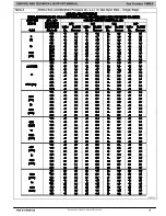
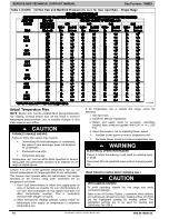
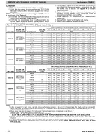
Table 3 (CONT.)
Orifice Size and Manifold Pressure (in. w.c.) for Gas Input Rate
−
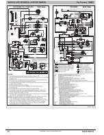
Single Stage
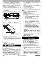
L12F047B
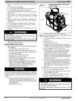
Adjust Temperature Rise
NOTE
: Blower door must be installed when taking temperature
rise reading. Leaving blower door off will result in incorrect
temperature measurements, due to possible changes in duct
static pressure and airflow.
FURNACE DAMAGE HAZARD
Failure to follow this caution may result in:
S
Overheating the heat exchangers or condensing
flue gases in heat exchanger areas not designed
for condensate
S
Shortened furnace life
S
Component damage
Temperature rise must be within limits specified on furnace
rating plate. Recommended operation is at midpoint of rise
range or slightly above.
CAUTION
!
Jumper R to W to check gas-heat temperature rise. Do not
exceed temperature rise ranges specified on unit rating plate.
This furnace must operate within the temperature rise ranges
specified on the furnace rating plate. Determine the air
temperature as follows:
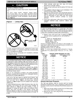
1. Place duct thermometers in return and supply ducts as
close to furnace as possible. Be sure thermometers do
not “see” heat exchangers so that radiant heat does not
affect thermometer readings. This is particularly
important with straight
−
run ducts.
2. When thermometer readings stabilize, subtract return
−
air
temperature from supply
−
air temperature to determine
temperature rise.
If the temperature rise is outside this range, check the
following:
1. Gas input rate.
2. Derate for altitude if applicable.
3. Return and supply ducts for excessive restrictions
causing static pressures greater than 0.50
−
in. w.c. (125
Pa)
4. Adjust temperature rise by adjusting blower speed.
S
Increase blower speed to reduce temperature rise.
S
Decrease blower speed to increase temperature rise.
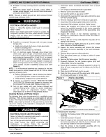
ELECTRICAL OPERATION HAZARD
Failure to follow this warning could result in personal injury
or death.
Disconnect 220 vac electrical power before changing speed
tap.
!
WARNING
(Read following caution before changing taps.)
UNIT DAMAGE HAZARD
To avoid operating outside the rise range and avoid
component damage:
Refer to the Air Delivery Tables to determine which airflows
and settings are allowed for proper heating airflow. DO NOT
use the highlighted settings for heating airflow. The
highlighted settings are to be used for Cooling and
Continuous Fan ONLY.
CAUTION
!