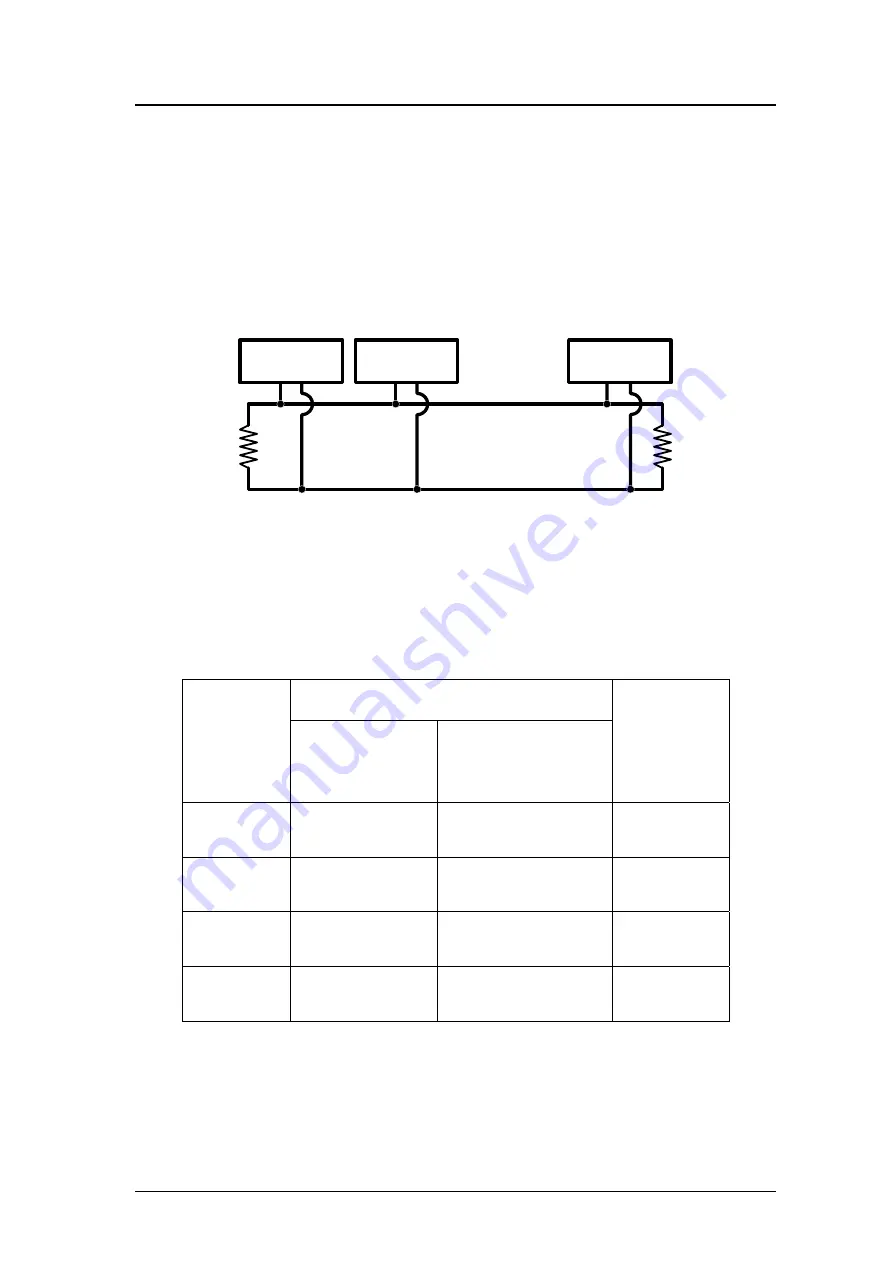
2.3.3 Wire connection
In order to minimize the reflection effects on the CAN bus line, the CAN
bus line has to be terminated at both ends by two terminal resistances as in the
following figure. According to the ISO 11898-2 spec, each terminal resistance
is 120
Ω
(or between 108
Ω
~132
Ω
). The length related resistance should have
70 m
Ω
/m. Users should check the resistances of the CAN bus, before they
install a new CAN network.
Ω
Ω
AN_H
AN_L
evice N
evice
evice
. . .
Figure 2.3.3 CAN bus network topology
Moreover, to minimize the voltage drop over long distances, the terminal
resistance should be higher than the value defined in the ISO 11898-2. The
following table can be used as a good reference.
Bus Cable Parameters
Bus Length
(meter)
Length Related
Resistance
(m
Ω
/m)
Cross Section
Terminal
Resistance
(
Ω
)
(Type)
0~40 70 0.25(23AWG)~
0.34mm
2
(22AWG)
124 (0.1%)
40~300 <
60 0.34(22AWG)~
0.6mm
2
(20AWG)
127 (0.1%)
300~600 <
40
0.5~0.6mm
2
150~300
(20AWG)
600~1K
PISO-DNS100(U) DeviceNet Slave API functions User’s Manual (Ver: 1.1) 2010/01/07
22
<
20 0.75~0.8mm
2
(18AWG)
150~300
Table 2.4 Relationship between cable characteristics and terminal
resistance
ГК
Атлант
Инжиниринг
–
официальный
представитель
в
РФ
и
СНГ
+7(495)109-02-08 [email protected] www.bbrc.ru


