


I-2533 User Manual (ver. 1.1, 2013/05/31) ------8
2.3 Pin Assignment
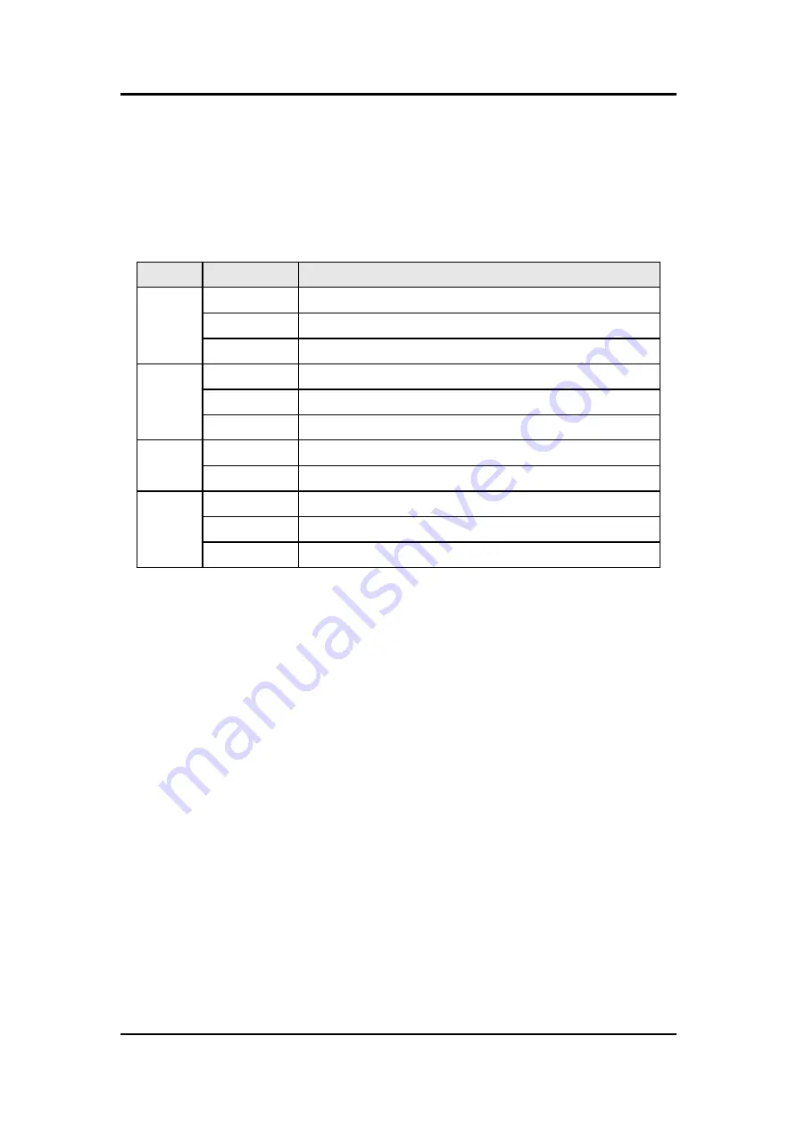
The pin assignments of COM port, CAN port, fiber port and power
connector of I-2533 are shown in the following tables.
Table 2-1 Pin Assignment
Port
Name
Description
COM
TXD
TXD pin of RS-232 port.
RXD
RXD pin of RS-232 port.
GND
SG (or GND) pin of RS-232 port.
CAN
CAN_L
CAN_Low, signal line of CAN port.
CAN_H
CAN_High, signal line of CAN port.
CAN_GND CAN_Ground, ground voltage level of CAN port.
Fiber
TXD
Transmit optic data.
RXD
Receive optic data.
Power
+VS
Voltage Source Input. +10V
DC
~ +30V V
DC
.
GND
Power Ground.
F.G.
Frame Ground.
Sometimes, the CAN_GND voltage level of different CAN devices on a
CAN bus system are not equal. In this case, it could cause some problems and
derogate the system stability. There is one way to relieve this situation; users
can connect the CAN_GND of different CAN devices with each other to
balance the voltage level of CAN_GND.
Electronic circuits are always influenced by different levels of
Electro-Static Discharge (ESD), which become worse in a continental climate
area. F.G. provides a path for conducting the ESD to the earth ground.
Therefore, connecting the F.G correctly can enhance the capability of the ESD
protection and improve the module
’s reliability.
Wiring of CAN_GND and F.G. is not necessary; users can modify the
configuration of wiring according to real applications.


